CityWave Assembly ManualUpdated 5 months ago
Pre-Assembly Tips
Welcome to the assembly manual for the Ridewave CityWave eBike. This guide will take you step-by-step through the process of assembling your new bike. Please read through the instructions carefully before starting to ensure a smooth assembly process. Bike will arrive 80% assembled (electronics are pre-assembled). Preparing your eBike is an exciting process! Here are some tips to ensure everything goes smoothly:
1. Keep a clean, open workspace for the assembly process.
2. Avoid using sharp tools near cables or wires to prevent accidental damage.
3. If you’re not confident assembling the bike, consider visiting a local bike shop for professional assistance.
Contents of the box
The box includes the following items:
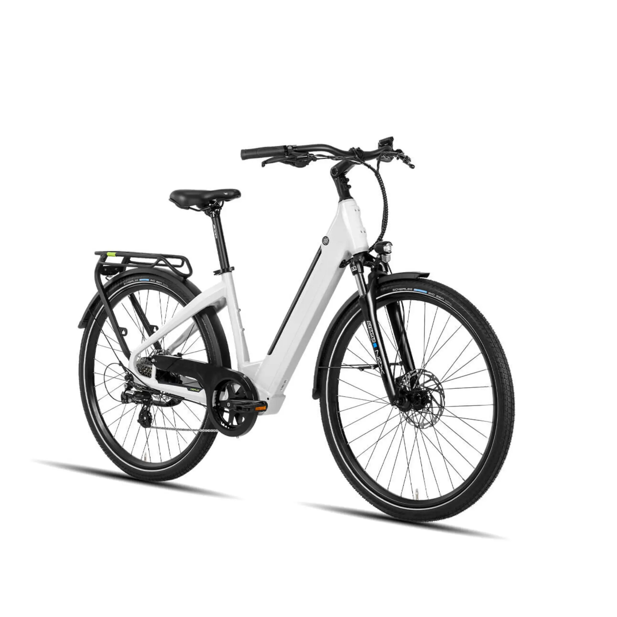
Ridewave CityWave eBike
User Manual
Battery charger
Maintenance grease
Battery keys
Pedals
Toolkit bag containing:
8/10mm Wrench
13/15mm Wrench
13/16mm Wrench
2.5mm Hex Key
3mm Hex Key
4mm Hex Key
5mm Hex Key
6mm Hex Key
7mm Hex Key
Step 1: Unpack the Bike
Opening the box: Carefully open the box using scissors or a Stanley knife. Avoid cutting too deeply to prevent damaging the bike or accessories. Remove the accessories box, which contains essential tools and components.
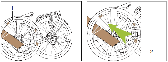
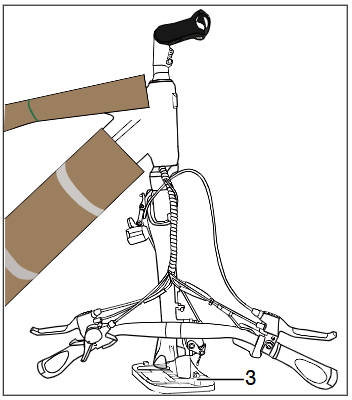
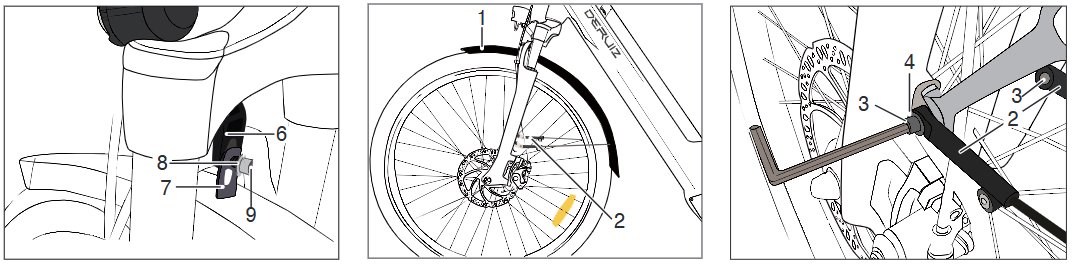
Getting bike ready for unfolding: After removing the accessories box, lift the bike out with assistance or cut the sides of the box to make it easier to access. Remove all protective materials (foam, cardboard, zip ties, and tape). Pay extra attention to avoid cutting wires while removing zip ties. Carefully remove the front wheel (1), making sure to avoid contact with the left crank. Stand the CityWave upright on the rear wheel (2) and the mounting stand (3).
Step 2: Attach Handlebars to Frame
Orienting head stem and forks: When packed in the factory, the forks will be facing backwards to compact the bike for packing. Lift the front of the bike and twist the head stem so that it faces towards the front of the bike. The brake caliper where the rotor will sit should be behind the forks on the left side of the bike.
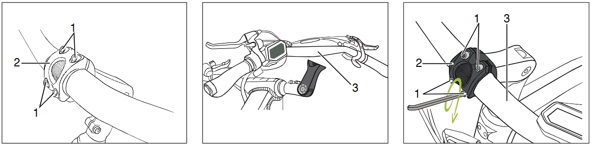
Attaching handlebars: Once the forks are aligned properly, use the 4mm hex key contained in the toolkit to loosen the 4 handlebar fixing bolts (1) on the handlebar clasp (2). Centre the handlebars (3) in position paying attention to the horizontal guidelines, these should not be visible on either side of the clasp once the handlebars are fixed in place. Tighten the handlebars in place with the 4 screws to 6Nm of torque.
Step 3: Assembling the front wheel
Preparing wheel: Ensure that the wheel is ready to be fixed to the front forks by removing all external cardboard packaging and cable ties. Remove the plastic mounting stand from the forks (1). This step can be made easier if the bike is inverted on it's handlebars, provided it is laying on it's cardboard box or some other soft surface to avoid scratching the frame. Remove the plastic spacer (3) from between the brake pads (4) in the front brake caliper (left fork).
- Inserting wheel into fork: Insert the front wheel into the fork dropouts, ensuring that the brake pads are correctly aligned with the rotor. Once the wheel is successfully in the dropouts, assemble the quick-release axle by positioning the spring on both sides. THE SPRINGS (5) MUST BE MOUNTED WITH THEIR NARROW SIDE FACING THE HUB/WHEEL.
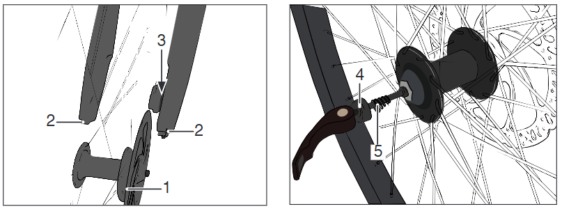
- Securing wheel safely: Tighten the axle nut and close the quick-release lever. The quick-release lever (7) must point upward and should close with noticeable resistance. WARNING: An improperly closed quick-release lever may open again. This can lead to severe accidents. Closing the quick-release lever must be difficult enough that it requires the use of your palm. Only then is the tension strong enough, approximately 15 kg.
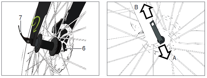
- POSITION A = OPEN, POSITION B = CLOSED
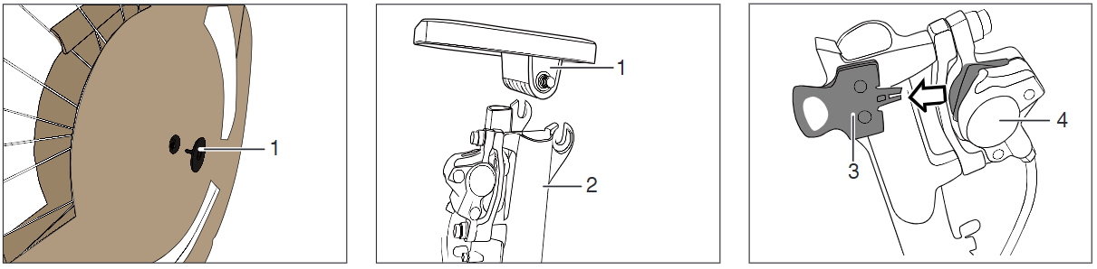
Step 4: Assembling Front Light and Front Fender
Front light assembly: Ensure that the arrows (1) on the headlight cable connectors align. WARNING: Misalignment may cause faulty connections, and the e-bike will not function. Disconnect the plug on the headlight cable (2). Reroute the headlight cable above the mount (3). Remove screw (4) using a 4 mm Allen key. Mount the headlight (5) with the fender bracket (6).
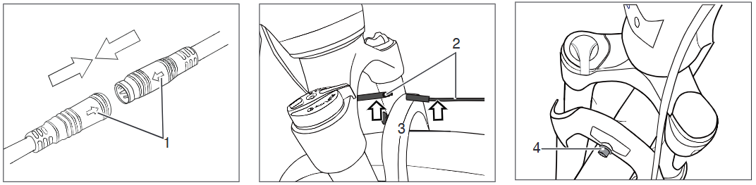
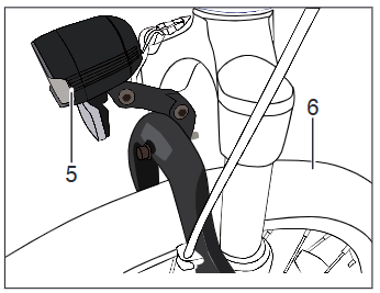
- Front fender assembly: Mount the headlight bracket (6) together with the fender holder (7), washer (8), and screw (9) using the 4 mm Allen key. Align the fender (1) with the struts (2). Secure screws (3) and washers (4) on both sides. Check the functionality of the front light by holding the plus button once the cables are connected and the bike is on.
Step 5: Pedal assembly
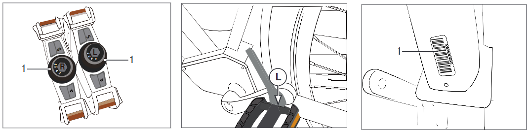
- Turning pedals: Grease the pedal threads (1). Screw in the left pedal (L) counterclockwise into the left crank. Screw in the right pedal (R) clockwise into the right crank. Tighten both pedals to 30 Nm using the 15 mm open-end wrench from the toolkit.
Note: The frame number (1) is located under the frame tube.
Step 6: Pumping the Tyres

- When preparing to pump the tyres:
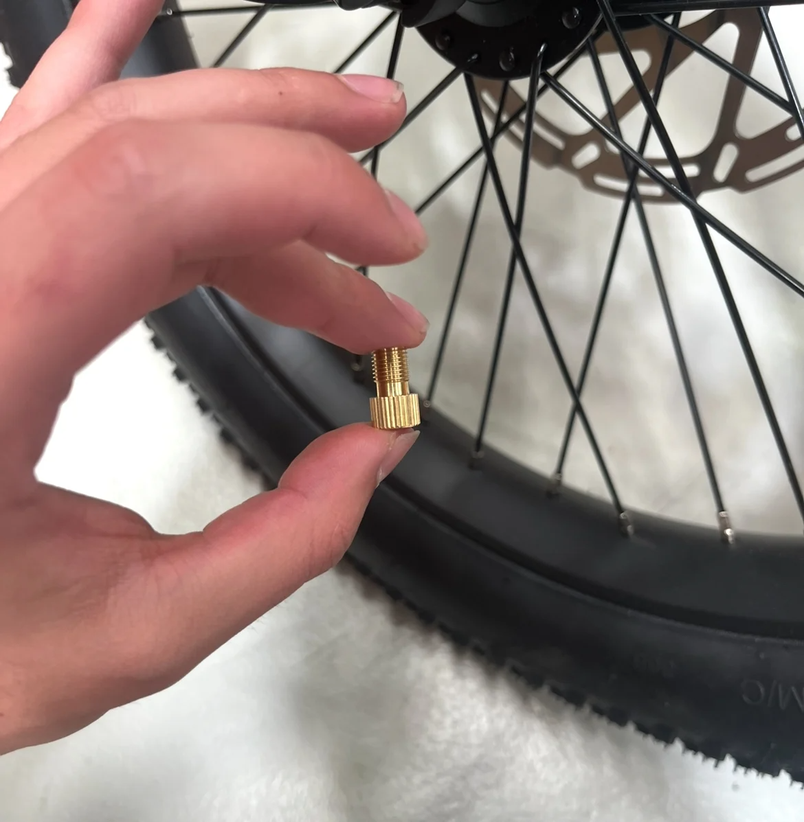
- Locate the valve adapter from within your CityWave box. The first picture in this step shows the valve adapter in my hands.
- Screw on the adapter to the valve as seen in the picture that follows. This now allows the tyres to be pumped by a standard australian nozzle.
- Use a tyre pump to inflate the tyres to the recommended PSI listed on the side of the tyres. For the CityWave, this is an inflation pressure of 35-70 PSI.
- Inflating tyres: Pump both the front and rear tyres to the pressure specified on the tyre sidewall. For the CityWave the recommended PSI is above.
- For a Softer Ride: A PSI range of 35-45 for a softer, more comfortable ride. This pressure is ideal for riders who frequently encounter uneven or off-road terrain.
- For a Firmer Ride: RECOMMENDED: If you prefer a sturdier and more responsive feel, aim for a PSI range of 45-70. Higher pressure reduces the frequency of pumping and is better suited for consistently flat terrain, such as urban roads.
- Finding Your Ideal PSI: Experiment with different pressure levels in the front and rear tires until you discover what feels best for your riding style and terrain. Adjust as needed to achieve your desired balance of comfort and performance.
Important:
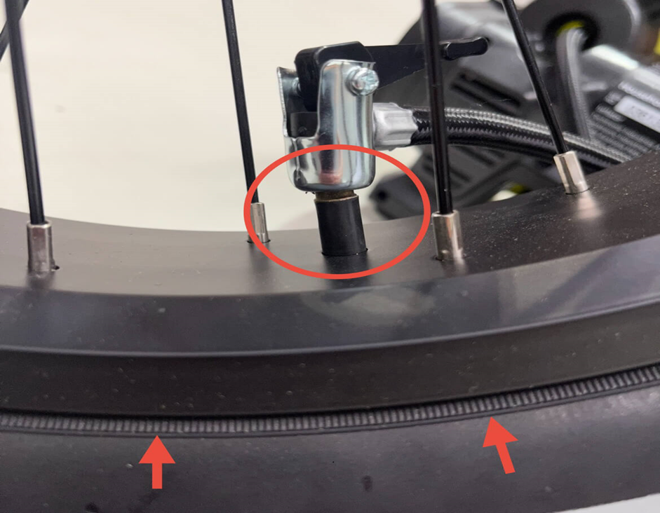
- While inflating, pause occasionally to check that the tyre bead (indicated with arrows) is properly seated around the rim.
- Ensure that the pumping nozzle is correctly attached to the inner tube valve, air should escape before the lever is adjusted. (Proper attachment circled in red)
- If the bead starts to rise unevenly, deflate the tyre slightly and press the bead back into place before continuing.
- Ensure the tyre bead line (a thin moulded line near the sidewall) is evenly positioned just above the rim on both sides.
- If any part of the inner tube becomes exposed during inflation, stop immediately as this can cause the tube to burst.
Properly seating the bead ensures safe and consistent tyre inflation.
Final Checks
Before riding your Ridewave CityWave eBike, perform the following checks:
- Ensure all bolts are tightly fastened.
- Check the tire pressure and inflate as needed.
Congratulations! Your Ridewave CityWave eBike is now fully assembled. Enjoy your ride and don’t hesitate to contact our support team for any additional assistance.