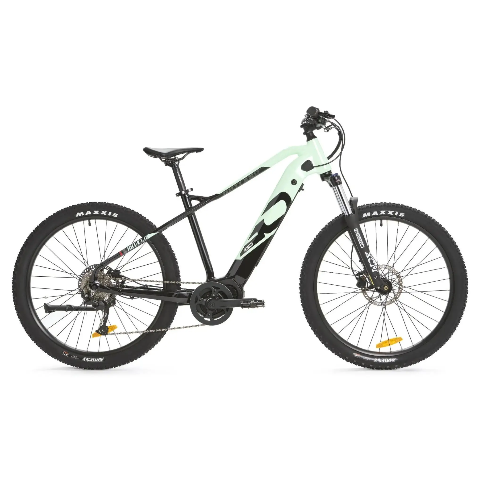
OutlandWave XT Assembly ManualUpdated 2 months ago
Preassembly tips
Preparing your Ridewave electric bike for the journey ahead is an exciting start! If you're not entirely comfortable with bike mechanics, consider having it professionally assembled at your local bike shop. Here’s a streamlined guide to get you going:
- Carefully cut only the packing zip ties to avoid damaging any important wires or cables.
- Pay attention to the plastic spacer in the front brake caliper. It keeps the brake pistons open when the wheel or spacer isn’t in place. Keep it handy for future wheel removals.
- Treat the brake rotors with care. Avoid touching them with your fingers to maintain their performance and prevent any unwanted noise.
- For a smooth and secure ride, apply grease to the pedal threads and a bit of anti-slip to the seat post before installation.
- Double-check that your fork is facing the right way. The brake caliper and rotor should be on the left side from the rider's perspective.
Following these steps ensures your Ridewave bike is ready for a seamless and thrilling ride. Enjoy every moment of your journey!
Step 1: Unpack the bike
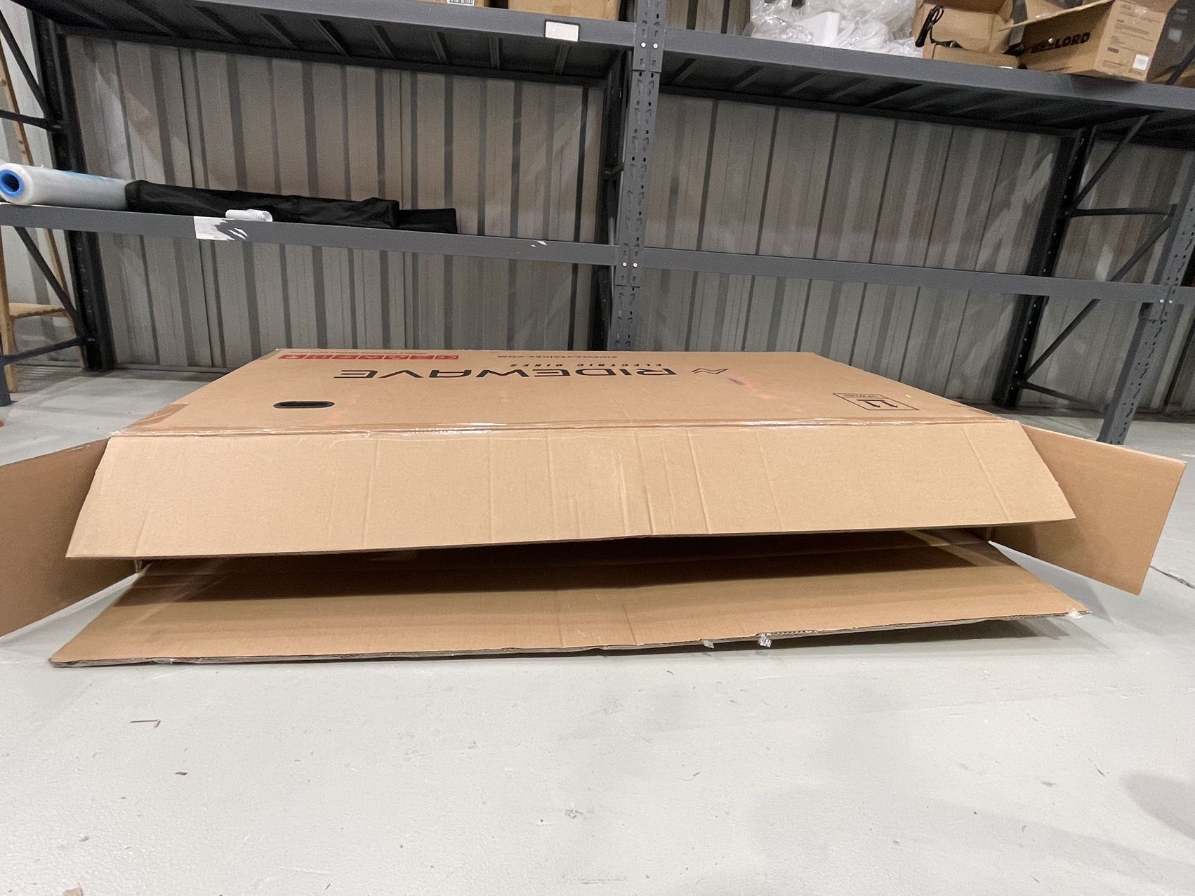
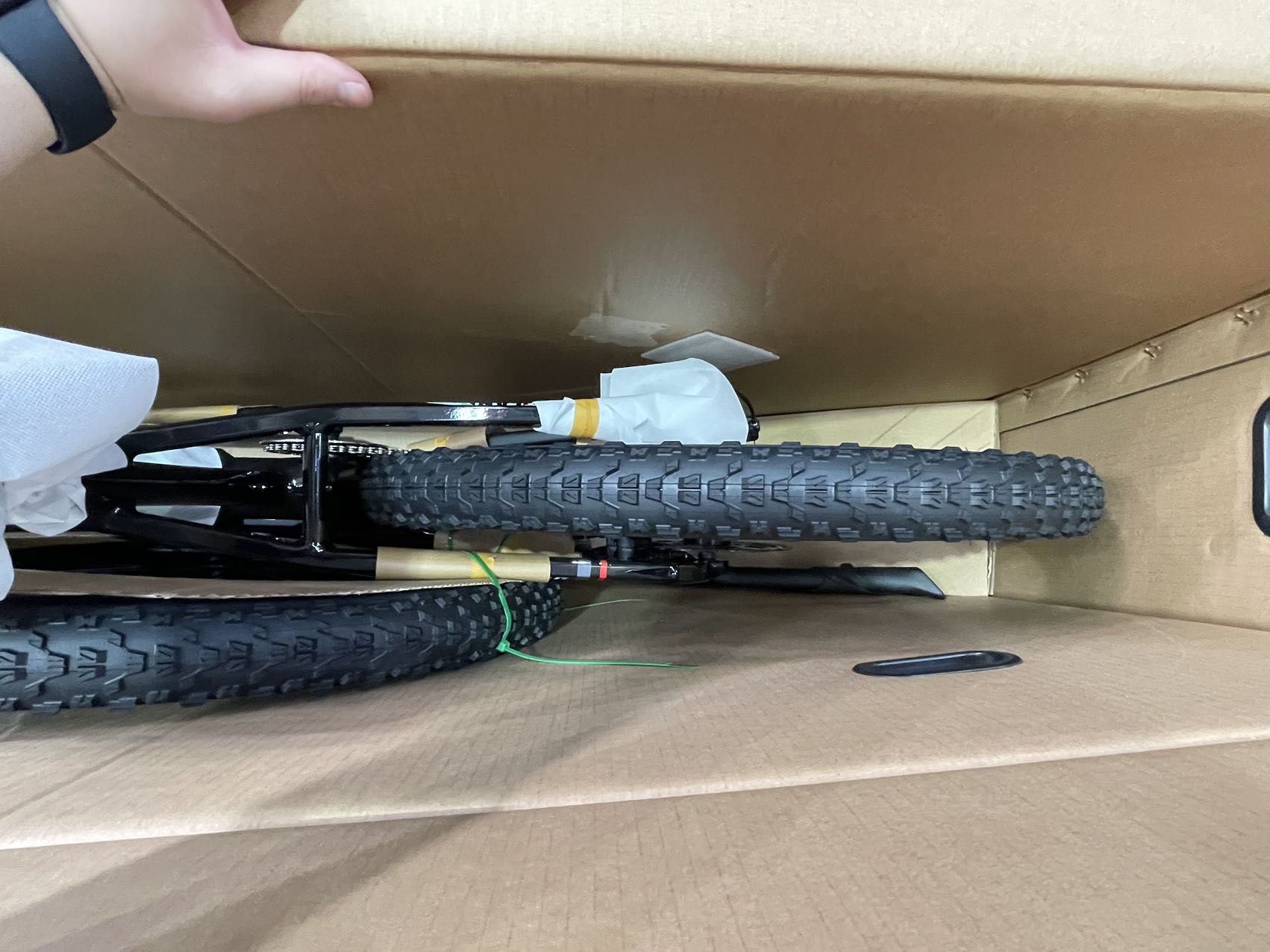
Remove the Bicycle from the Box: Begin by carefully removing the bicycle from the box; this can be easier if a second person holds the box while the first person lifts the bicycle. Cut the packing material away from the bike, only cutting the green cable ties necessary to remove the protective packaging from the bicycle frame. Cut the packing material away from the bike. Only cut the green cable ties needed to remove the protective packaging from the bicycle frame.
If assembling alone and removing the bicycle from the box is difficult, lay the box on its side with the side that has the kickstand facing the ground. Then, use a utility knife to carefully open the side of the box, creating enough space to slide the bicycle out safely.
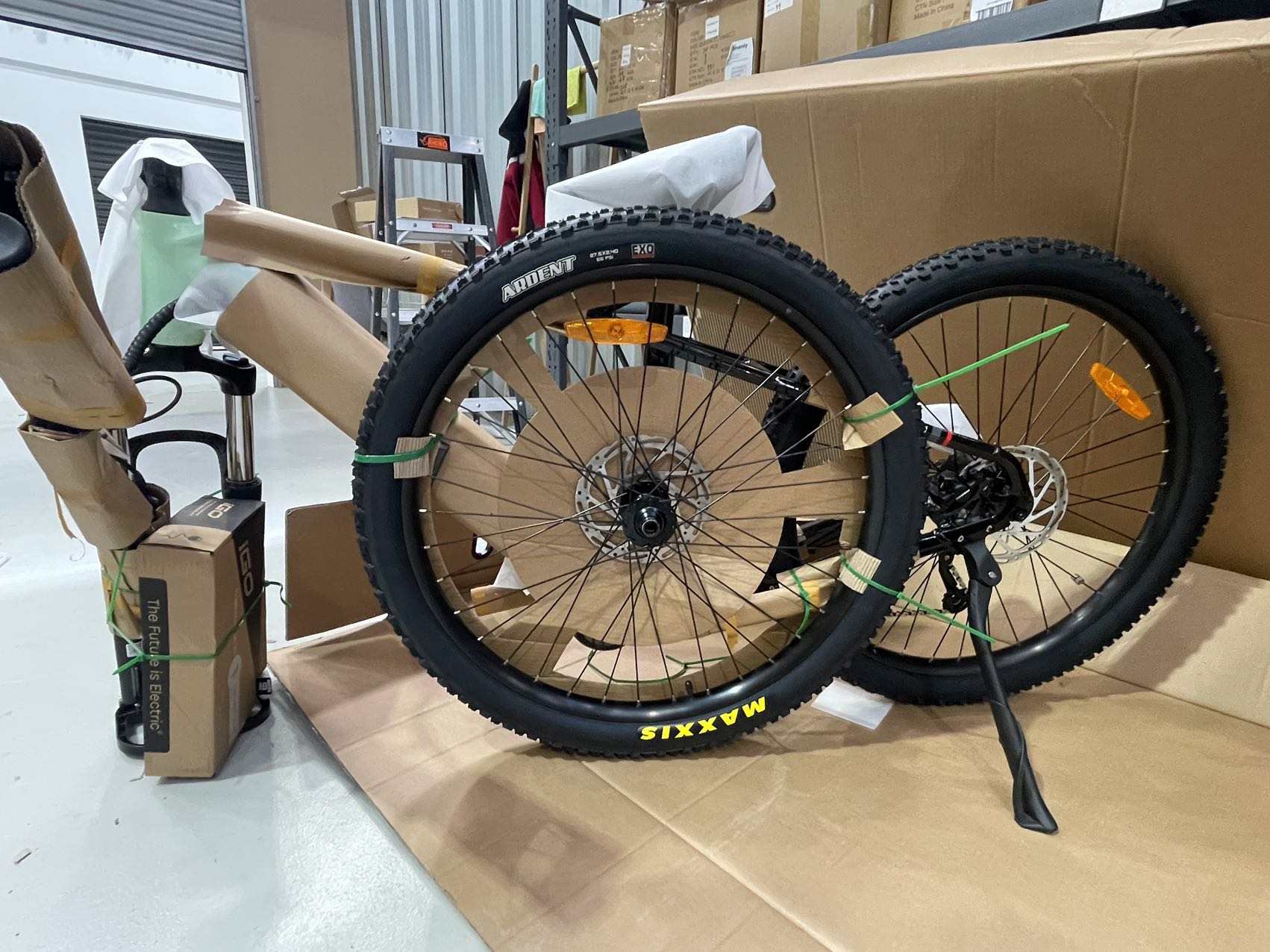
Step 2: Open the Parts Box
After cutting the zip ties, remove the parts box from the bicycle box and open it. The photo below displays all the components we now have.
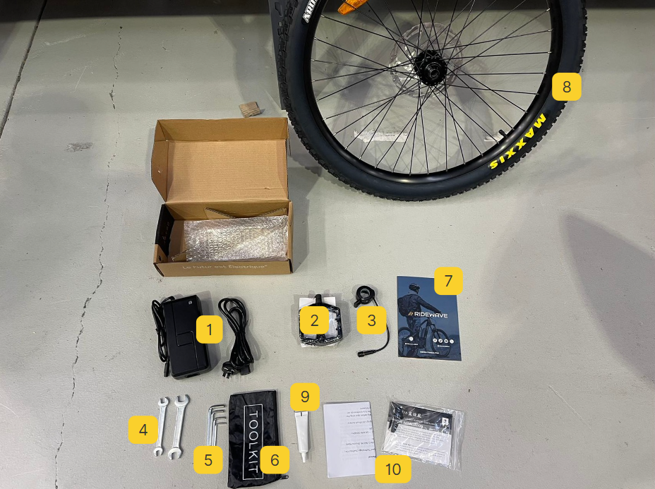
- Charger
- Pedals
- throttle kit
- Open-end wrenches/ spanners
- Hex Keys
- Tool Kit Bag
- Ridewave Brochure
- Front Wheel
- Anti-seize grease
Step 3: Install the seat post
The seat post is pre-installed for OutlandWave XT, so you only need to adjust it to your preferred height with a tool after completing the bike assembly.
Step 4: Install the handlebar
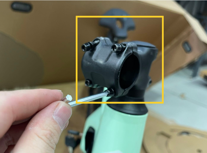
Remove the Bolts: Begin by using a suitable 4mm hex key or wrench to remove the four bolts shown in the images. These bolts secure the handlebar clamp.
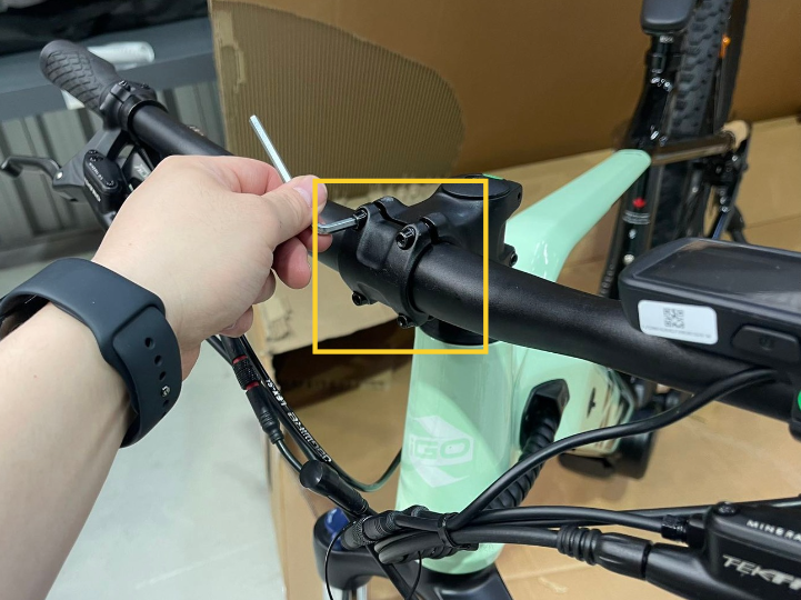
Position the Handlebar: Place the handlebar in the correct position on the stem. Ensure it’s centered and at the desired angle for comfortable riding.
Attach the Handlebar Mount Cover: Align the handlebar mount cover over the handlebar, matching the holes with the bolt slots.
Reinsert and Tighten the Bolts: Insert the four bolts back into their positions through the handlebar mount cover. Initially, only tighten the bolts loosely, allowing for some adjustment. Adjust the handlebar angle to ensure the front of the bike is aligned correctly. Once aligned, tighten the bolts fully in a cross-pattern (top-left, bottom-right, top-right, bottom-left) to ensure even pressure on the handlebar.
Check the Alignment: After securing the bolts, connecting the cable, and adjusting the headlight, double-check the alignment of the handlebar to make sure it’s straight. Make any final adjustments as needed.
Step 5: Install the front wheel and fender
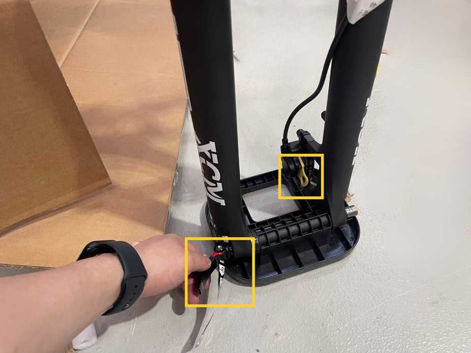
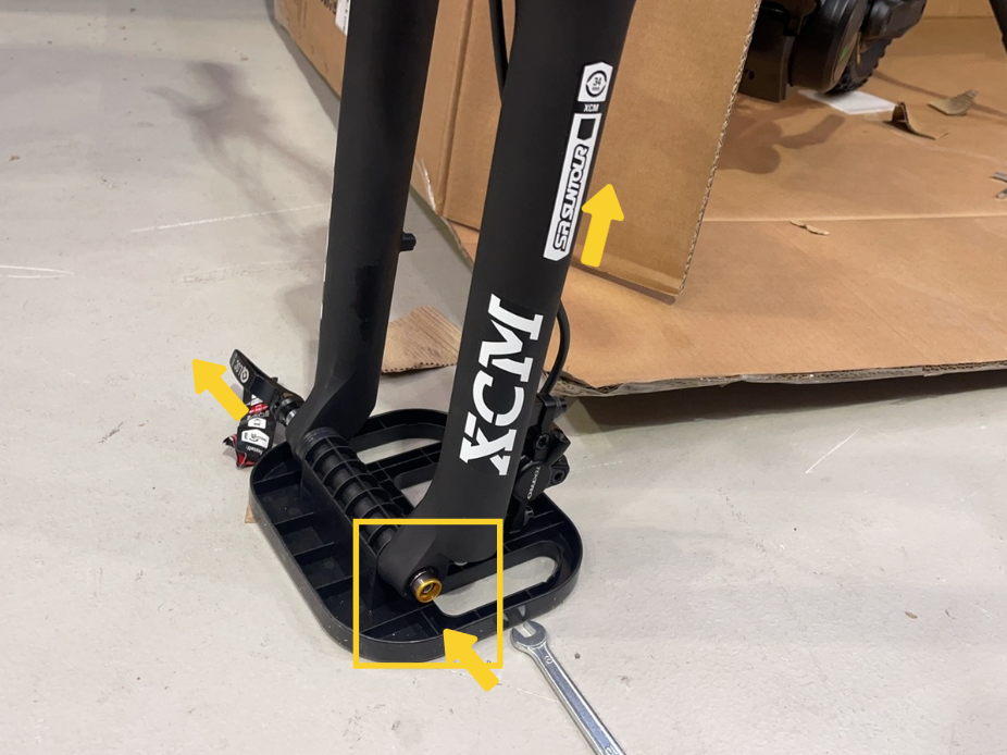
Flatten the Quick Release Handle: Start by folding the quick release handle down flat. Then, rotate it counterclockwise to loosen it.
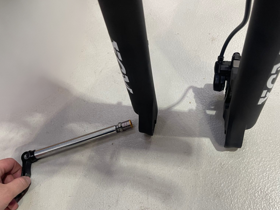
Push from the Opposite Side: Once the handle is loose, go to the opposite side of the quick release and gently push the axle with your hand. At the same time, lift the front of the bike slightly so that the weight is not pressing down on the mounting base. This will make it easier to slide the quick release axle out without obstruction.
Remove the Brake Pad Spacer: Take out the brake pad spacer from the front wheel disc brake (highlighted in the first image). This step is necessary to prepare for installing the front wheel.
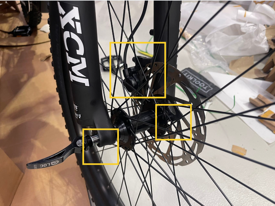
Align the Disc Brake Rotor: Carefully position the front wheel so that the disc brake rotor (the metal disc) aligns with the brake caliper (highlighted in the left image). The rotor should slide smoothly between the brake pads without touching either side.
Insert the Axle into the Fork Dropouts: With the rotor aligned, position the wheel so that the axle fits into the fork dropouts on each side. Make sure the axle is fully seated and the wheel is centered within the fork (as shown in the right image).
Secure the Quick-Release Axle: After aligning and seating the wheel correctly, close the quick-release tension lever by rotating it clockwise until it feels snug. Then, push the lever inward to lock it securely. Ensure that the lever is tight enough to hold the wheel stable and centered, but not overly tight, which could make it difficult to release in the future. THE TENSION LEVER SHOULD TAKE A REASONABLE AMOUNT OF FORCE TO CLOSE TO ENSURE THE WHEEL WILL REMAIN SECURED IN THE BIKE, IF THE LEVER CLOSES TOO EASILY ROTATE IT CLOCKWISE WITH A HALF-ROTATION AND TRY TO CLOSE THE LEVER AGAIN.
Step 6: Install the pedals
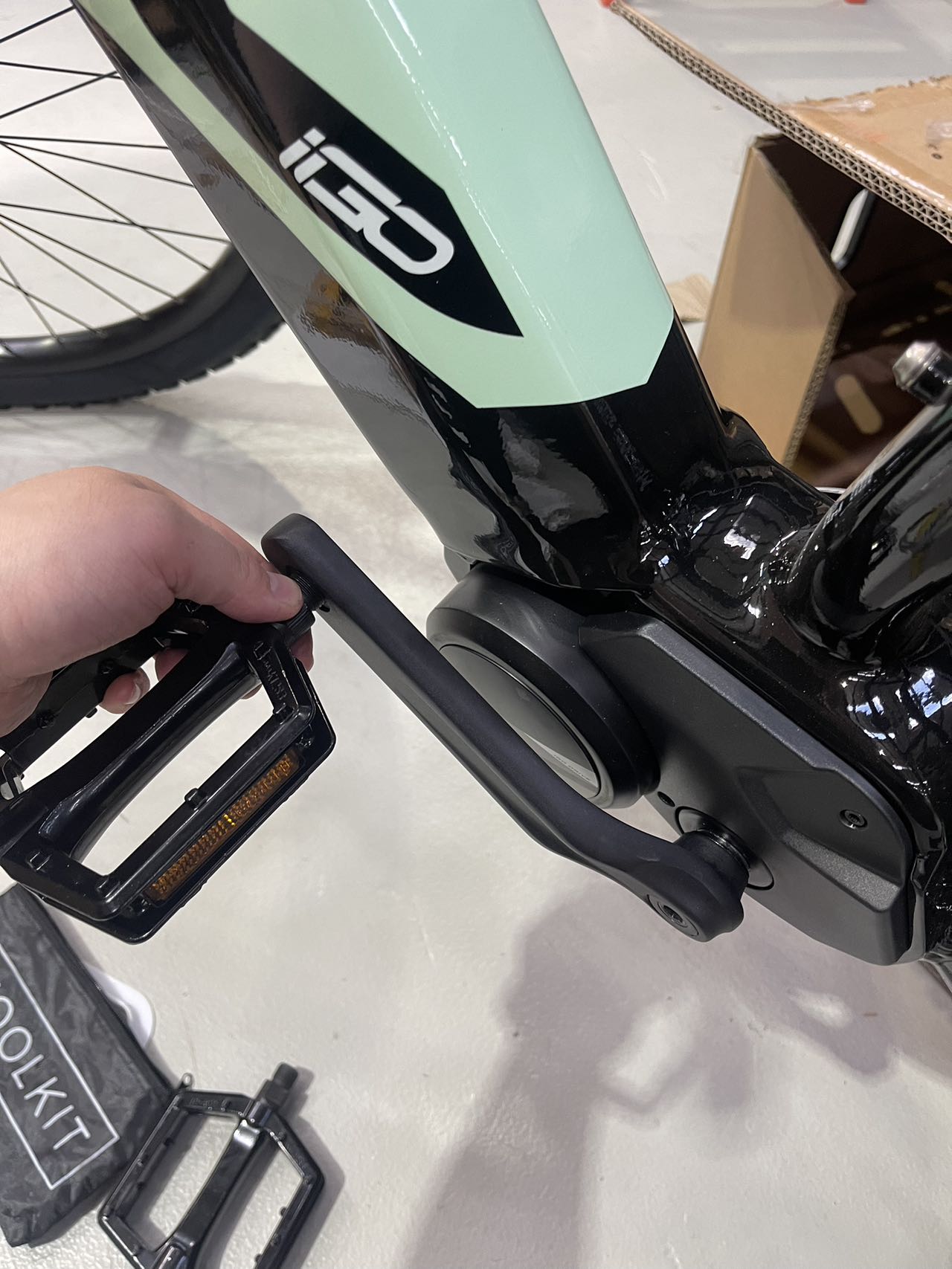
Apply Grease to the Pedal Threads: Begin by applying a small amount of grease to the threads of the pedal, as shown in the image. This helps prevent seizing and makes future removal easier.
Attach and Tighten the Pedals: Insert the pedal into the crank arm and hand-tighten it to ensure it’s threaded correctly. Then, use an open-ended 15mm wrench to securely tighten the pedal. Be sure to tighten each pedal in the correct direction: the right pedal (R) tightens clockwise, and the left pedal (L) tightens counterclockwise.
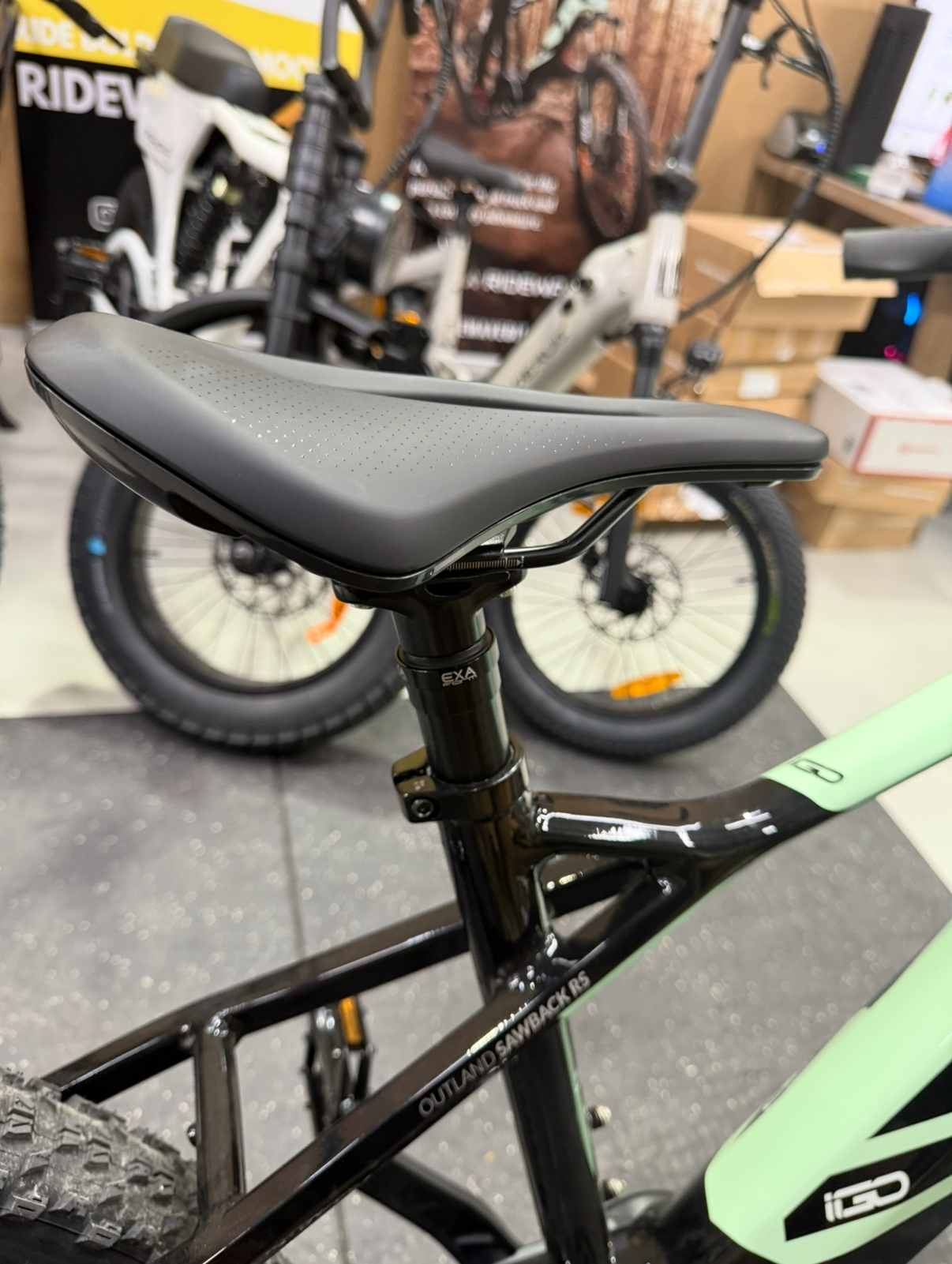
Step 7: Setting up the dropper post
- Use a 5mm Allen key to loosen the seatpost clamp bolt. Gently raise the seatpost by about 5–7cm, or until you begin to see the cable tension being taken up at the dropper post lever. Adjust the post to a height that makes sense for your lowest riding position (this sets the travel limit). Once you're satisfied with the height, retighten the clamp bolt firmly.
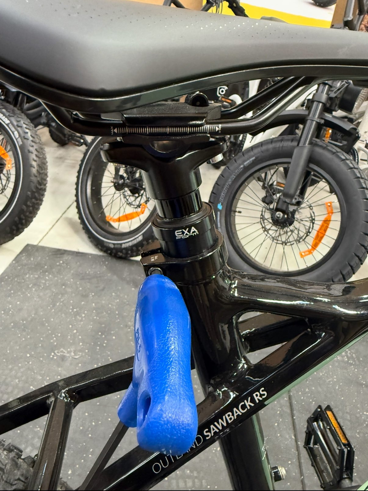
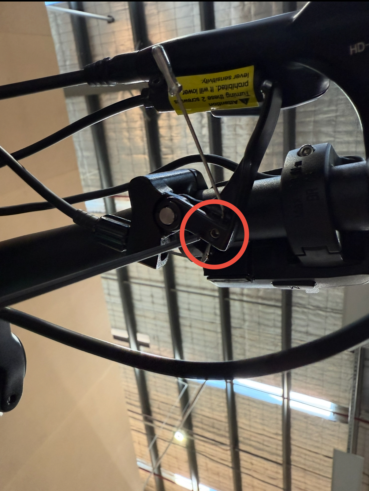
- Underneath the dropper post lever, use a 2mm Allen key to loosen the cable pinch bolt—this is the small bolt holding the cable in place inside the lever mechanism. Once loosened, gently pull the cable taut from the exposed end. NOTE: Be careful not to pull on the metal end cap (the crimped tip), as it can come off. Instead, hold the cable just above the cap using your fingers or a pair of pliers with light pressure.
- If the cable feels stuck or isn’t moving freely:
- With the cable pinch bolt loosened, fully press the dropper lever with one hand—this helps release tension inside the mechanism.
While holding the lever down, pull the cable tighter with your other hand.
Then, while still holding the cable tight, slowly return the lever to its resting (closed) position.
This will help trap the cable in the correct position with minimal slack.
Retighten the cable pinch bolt using the 2mm Allen key.
Step 8: Attaching the throttle (Optional):
Note: The throttle is only to be used on private-property or for off-road use. It is ILLEGAL to use throttle-power exceeding 6km/h on public roads in most states in Australia, and this throttle has no way of being limited to this speed. Please refer to our manual here for more information.
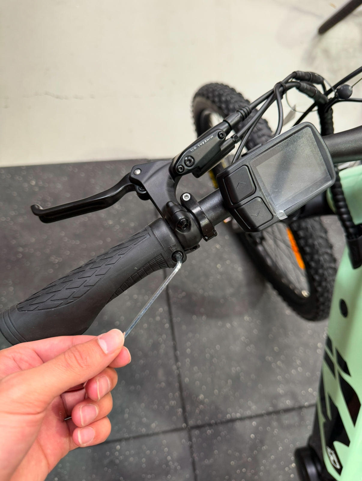
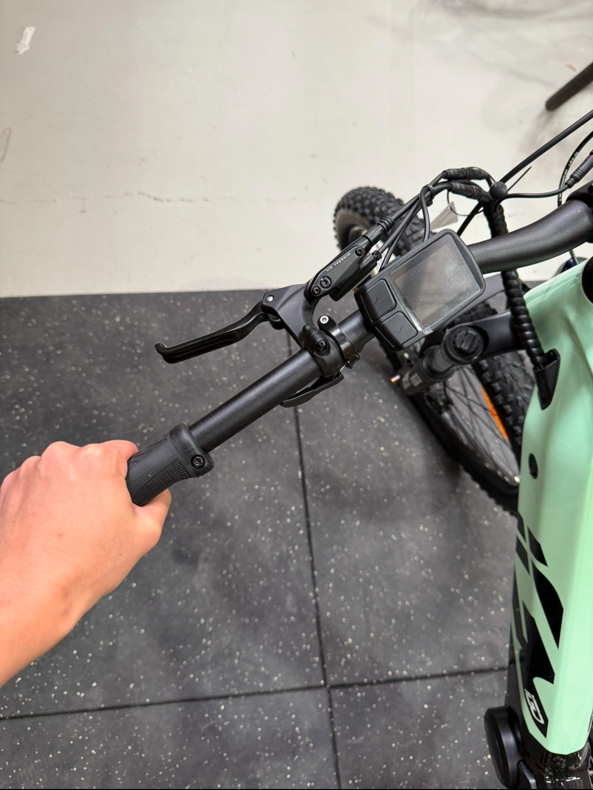
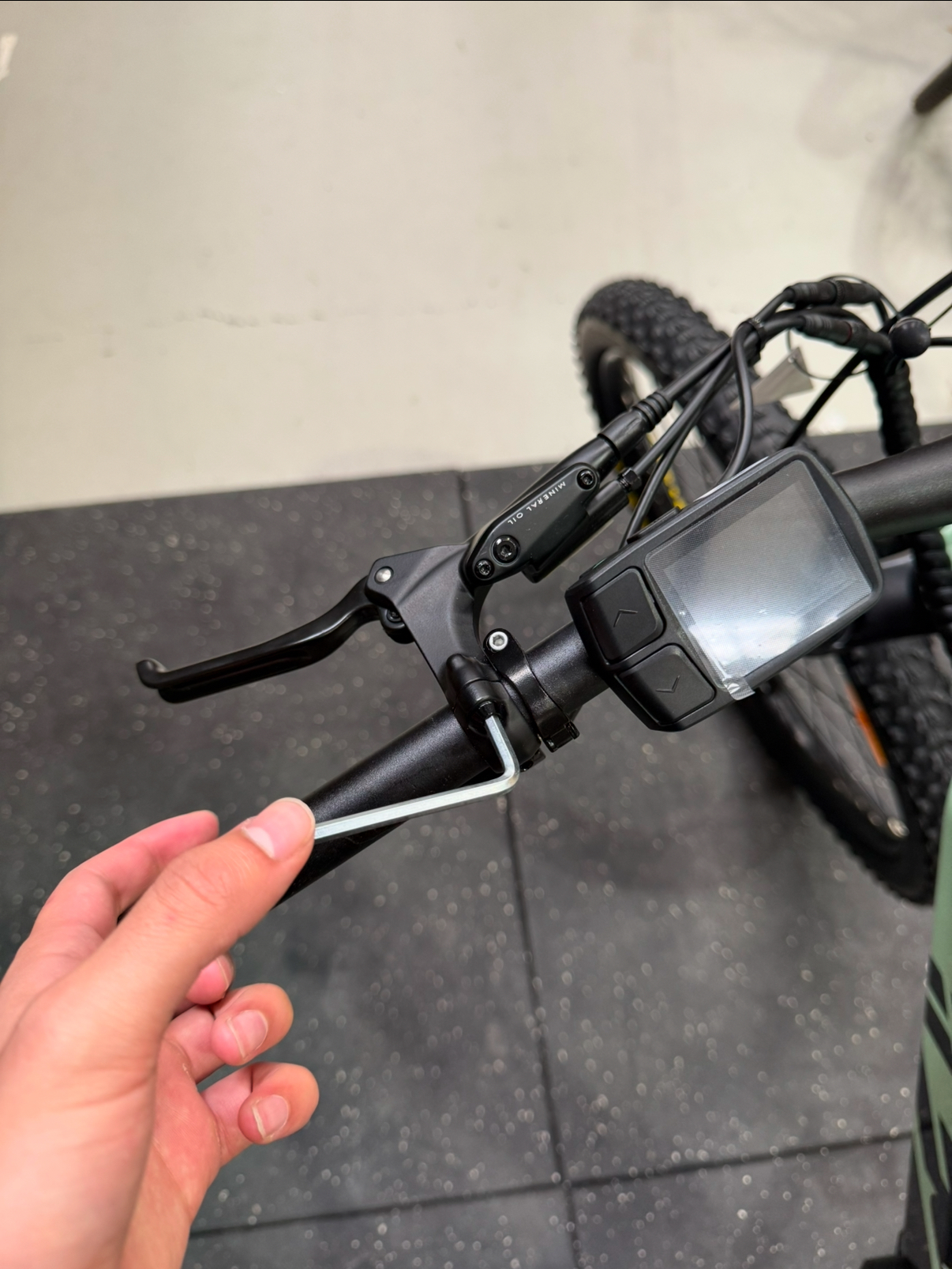
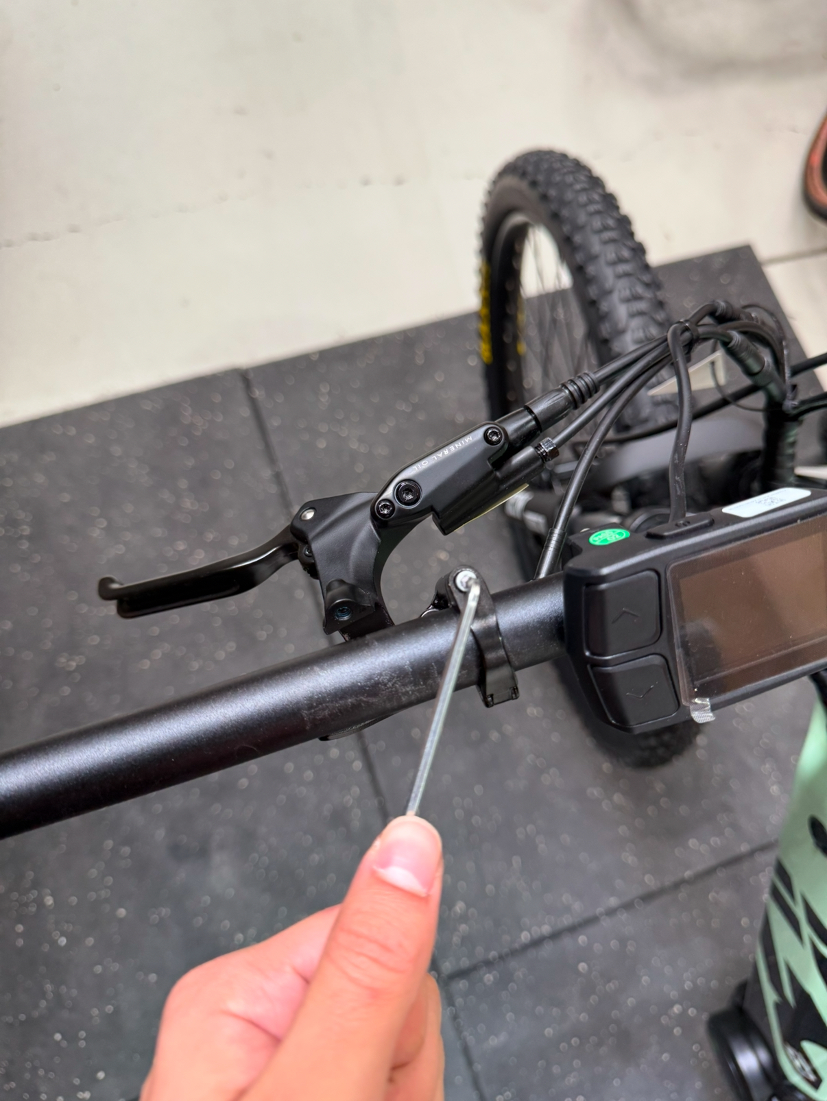
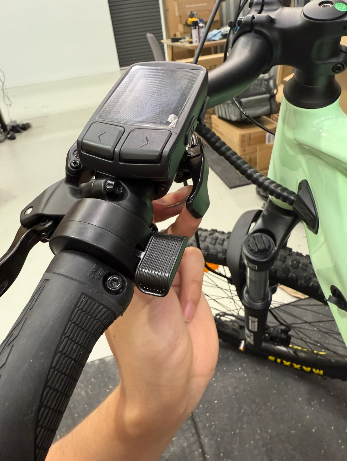
Remove handlebar attachments: Use a 3mm hex key to loosen the bolt holding the grip on the handlebar. Slide the grip off. With a 4mm hex key, loosen and remove the bolts securing the brake lever to the handlebar. Do not slide it off – the tension in the cables is high. Let the brake lever hang instead. Use the 3mm hex key again to loosen the bolt for the seat dropper lever so it can move freely or be removed. Lastly, use a 2.5mm hex key to remove the display bolt, allowing the display to hang or be removed from the handlebar.
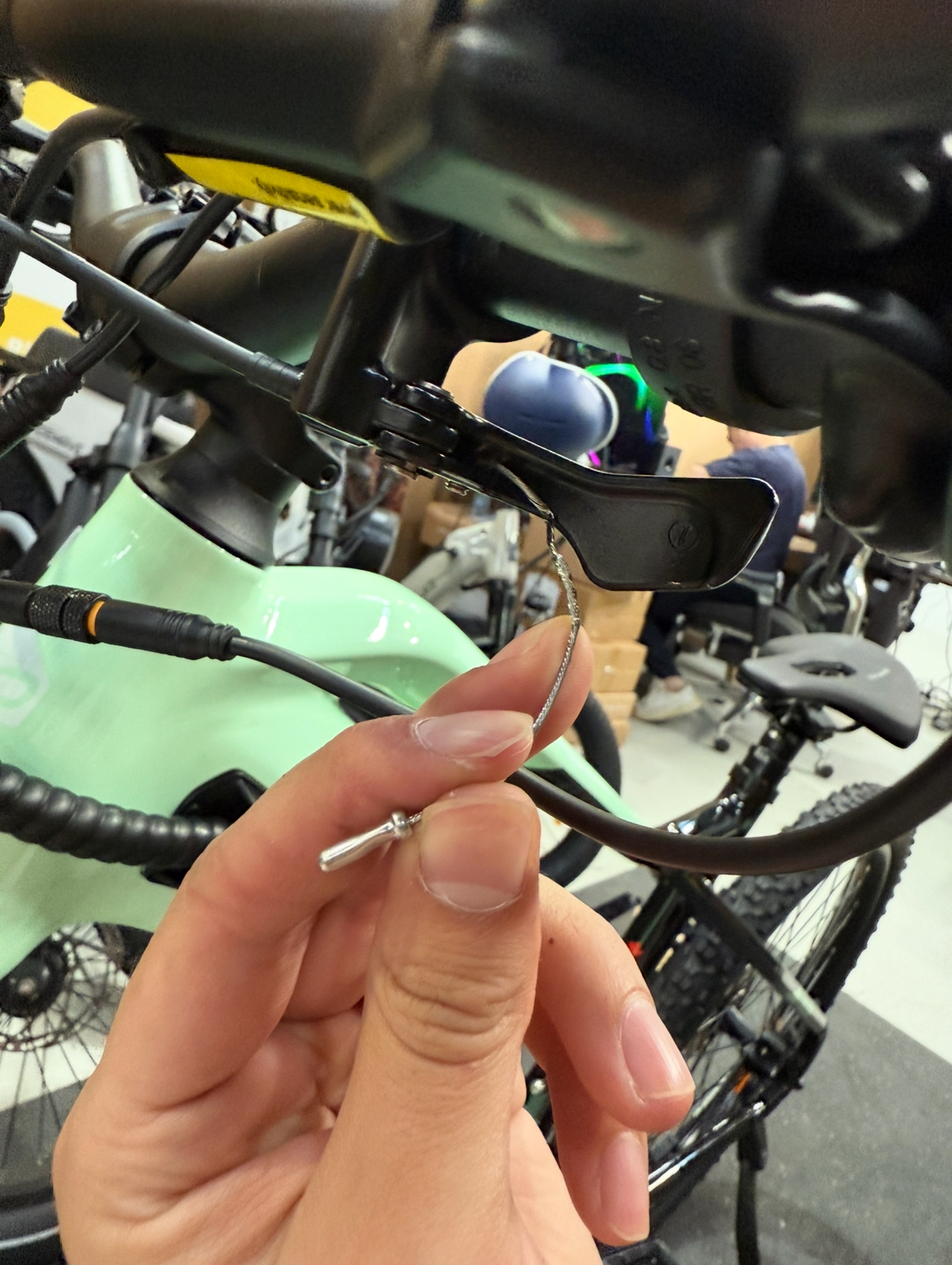
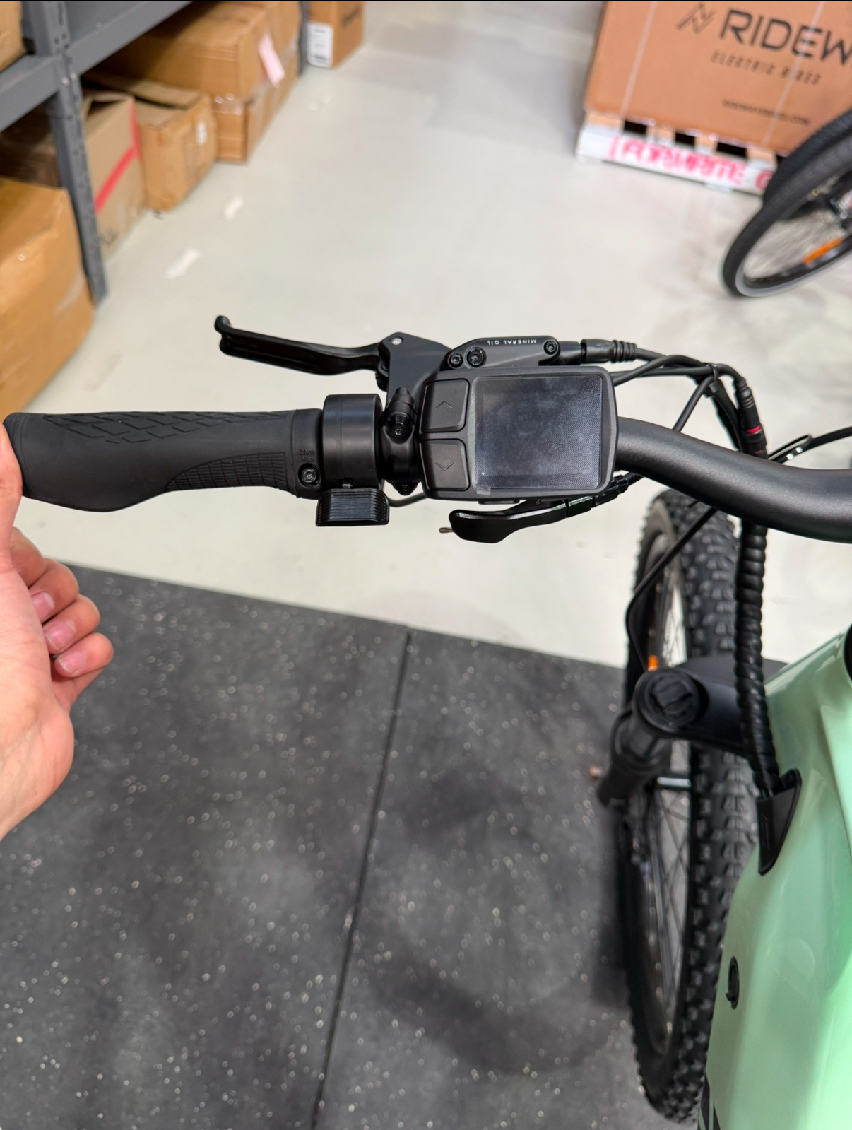
Find throttle position: Slide the throttle onto the handlebars so the thumb lever faces towards you (the rider). The thumb lever should sit close to the right side of the brake lever. Reattach the brake lever directly to the right of the throttle, as seen in the photos above. Leave everything loose for now to give yourself space to adjust and reposition. Attach the seat dropper lever first, ensuring the thumb throttle and seat dropper levers do not interfere with each other. Screw the display back on, positioning it above the seat dropper lever. Ensure the handlebar grip is fully slid back onto the bar – there should be no gaps where you can’t feel the metal underneath.
Connect cable: Refer to the final image for the correct order and position of all the attachments. Connect the yellow throttle cable, ensuring the arrows on the connectors face each other. Once aligned, screw the connectors together securely.
Final checks: Ensure all attachments – grip, brake lever, throttle, seat dropper, and display – are in their correct positions and tightened securely. Check for smooth movement of all levers and controls to avoid interference while riding. Confirm that the throttle and display are firmly in place, and the handlebar grip feels solid.
Final Steps & Adjustments:
- Bolt covers: Attach the plastic bolt covers to the rear wheel motor bolts to protect them.
- Inflate the tyres: Check the recommended tyre pressure on the side of the tires and inflate to your liking. For the OutlandWave XT, the recommended PSI is 35-65 PSI, a lower PSI will mean a softer ride, slightly more suited to uneven terrain whereas a higher PSI is better suited for roads and consistent terrain.
- Adjusting the seat: Use the quick-release lever to loosen the seat post and adjust it to a suitable height and orientation for your needs. Observe the guidelines on the seatpost to ensure you don't exceed the maximum height.
- Adjusting handlebars: If handlebar position is uneven or uncomfortable, it is worth loosening the four bolts fixing the face plate to the handlebar stem using a 4mm hex key. The handlebars can now be moved freely into a more comfortable position, once satisfied tighten the bolts until the handlebars are fully secured.
Once the bike is assembled, it will need some fine-tuning and basic adjustments. The following links are the most common areas needing adjustment within the first few miles.
Adjust the derailleur- https://www.parktool.com/en-us/blog/repair-help/rear-derailleur-adjustment
Bed the brakes- https://www.youtube.com/watch?v=iUV2Eo9ERSk
Adjust the brakes- https://www.youtube.com/watch?v=uk_nC9anQcM
For any further questions, please reach out to support via the contact form: https://ridewavebikes.com.au/pages/contact-us