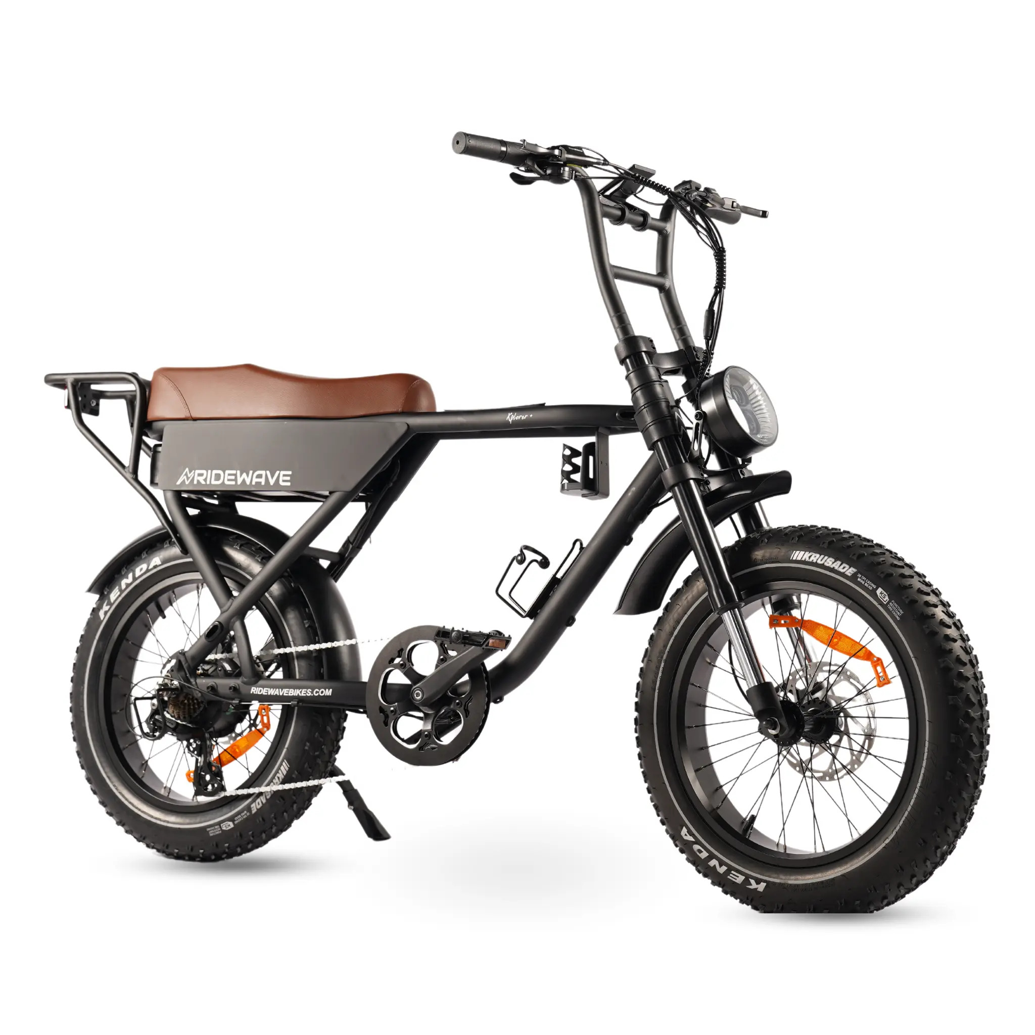
Xplorer Plus Assembly ManualUpdated 6 months ago
Pre-assembly tips
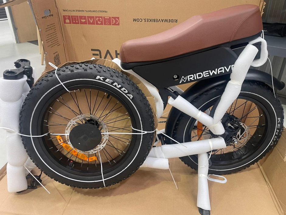
Preparing your Ridewave electric bike for the journey ahead is an exciting start! If you're not entirely comfortable with bike mechanics, consider having it professionally assembled at your local bike shop. Here’s a streamlined guide to get you going:
Carefully cut only the packing zip ties to avoid damaging any important wires or cables.
Pay attention to the plastic spacer in the front brake caliper. It keeps the brake pistons open when the wheel or spacer isn’t in place. Keep it handy for future wheel removals.
Treat the brake rotors with care. Avoid touching them with your fingers to maintain their performance and prevent any unwanted noise.
For a smooth and secure ride, apply grease to the pedal threads and a bit of anti-slip to the seat post before installation.
Double-check that your fork is facing the right way. The brake caliper and rotor should be behind the forks on the left side from the rider's perspective.
Following these steps ensures your Ridewave bike is ready for a seamless and thrilling ride. Enjoy every moment of your journey!
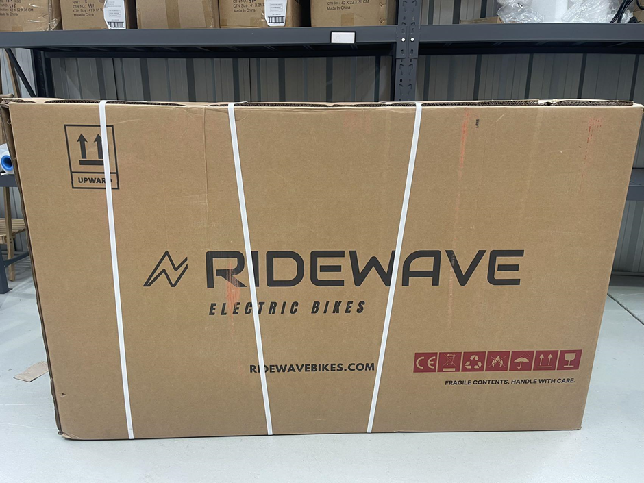
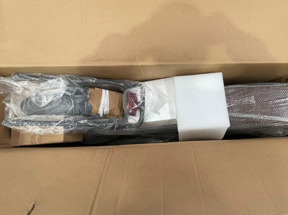
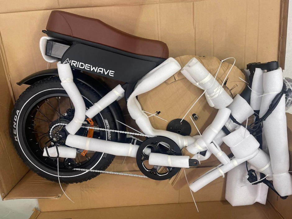
Step 1: Unpack the bike
- Tools required:
- Scissors/Cable Cutters
- Remove External Packaging – Carefully remove any remaining protective packaging, including foam and plastic wrap. Only cut the white cable ties necessary to free the bike from its packaging. Be cautious around the key for the battery lock, which is secured with a thin black cable tie. Cut this black tie carefully, ensuring you do not accidentally cut any other wires.
- For One Person – Position the box so that the kickstand side (LEFT SIDE) is facing downward to protect the gear side. Carefully cut open the box from the side to make removal easier. Once the box is open, use the bike’s kickstand and lean it against a wall to keep it upright and stable for the next steps.
- For Two People – If you have assistance, both people can work together to lift the bike out of the box after removing all securing materials. This balanced approach minimizes the risk of damage.
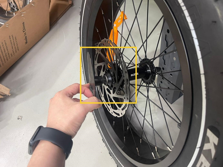
- Remove the Front Wheel Protector – After cutting the cable ties securing the front wheel, you’ll find a plastic protective cover on the wheel axle. Slowly remove this cover. Sometimes, a bolt may be stuck inside the protector; if this happens, use a screwdriver to gently pry it out. This bolt is a necessary component for securing the front wheel, so before discarding the protective cover, make sure you don’t accidentally throw the bolt away.
Step 2: Open the Parts Box
After cutting the zip ties, remove the small parts box from the bicycle box and open it. The photo below displays all the components we now have.
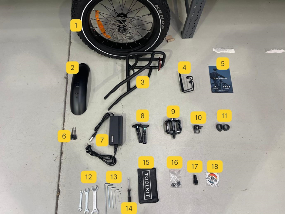
- Front Wheel
- Front Fender
- Rear Rack
- Bottle Holder
- Ridewave Brochure
- Key Set for Battery
- Charger
- Foot Pegs
- Pedals
- Bike Bell
- Handlebar End Caps
- Open-end wrenches/spanners
- Hex Key Sets
- Screwdriver
- Tool Kit Bag
- Spare Bolts And Washers
- Mini touch-up paint
- Free Custom Bike Stickers
Step 3: Charging the Battery
Since assembling other parts of the bike will take some time, this is a good opportunity to start charging the battery. Please follow these steps carefully to protect the battery and charger from potential damage.
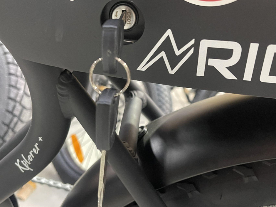
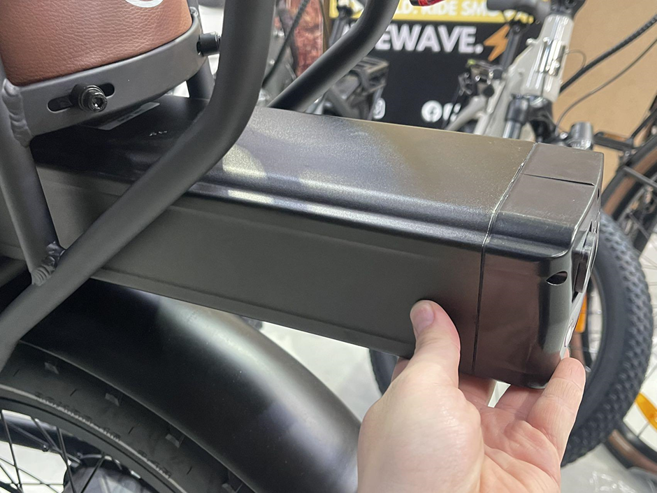
- Unlock and Remove the Battery – Insert the key into the keyhole and turn it counterclockwise to unlock the battery. Once unlocked, gently pull on the rear end of the battery, as shown in the previous image, to slide it out from the frame. The battery will detach from the terminals and slide out straight back from its base if it is successfully unlocked.
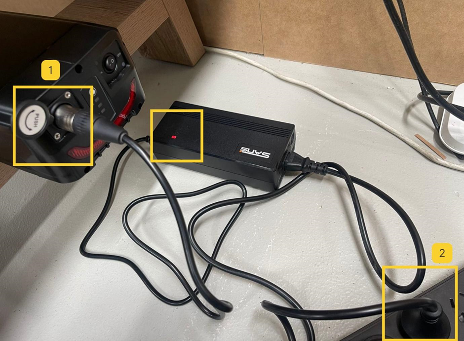
- Connect the Charger to the Battery First – Begin by plugging the charger into the battery (labeled as 1 in the current image). Make sure the connection is secure.
- Plug into the Power Outlet – After the charger is securely connected to the battery, plug the charger into the power outlet (labeled as 2 in the image). This order helps protect the battery by preventing sudden surges of current.
- Check the Indicator Light – Look at the indicator light on the charger. If the light is red, it means that charging has started and the battery is currently being charged. When the light turns green, it indicates that the battery is fully charged and ready for use.
- Ending the Charge – When charging is complete, follow a similar process in reverse. First, turn off the power at the outlet and unplug the charger from the power point. Then, disconnect the charger from the battery.
- Important: Always follow this charging sequence strictly. Incorrect order can increase the risk of damage to either the battery or the charger.
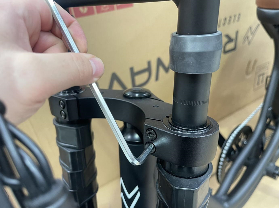
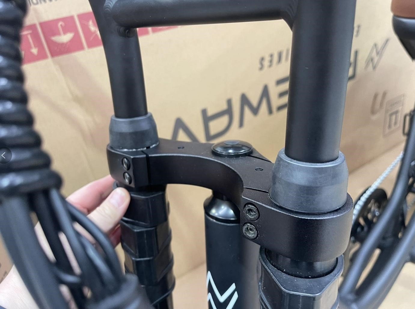
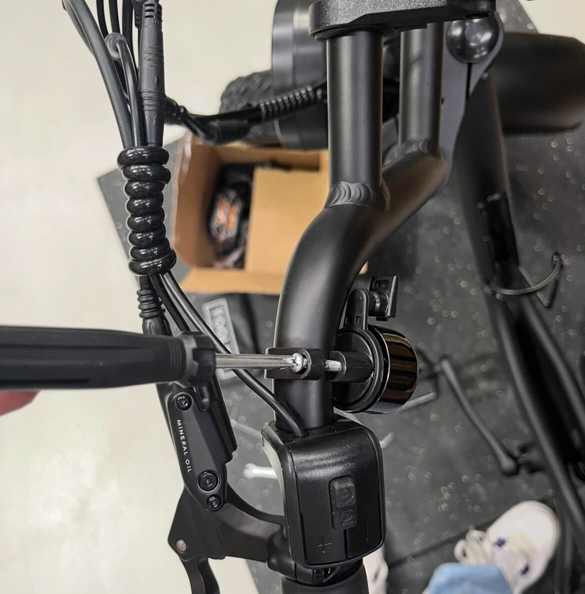
Step 4: Install the handlebars
Follow these steps to securely install the handlebars:
- Tools required:
- 4mm Hex Key
- 4mm Hex Key
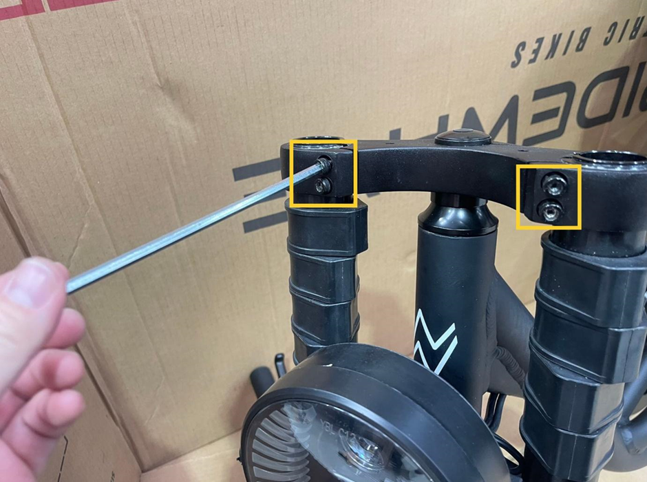
- Loosen the Bolts – Using a hex key, carefully loosen the four bolts on the handlebar clamp (as shown in the first image). This will allow you to insert the handlebar into the clamp.
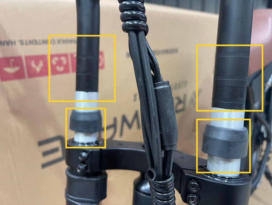
- Attach the Handlebar End Caps – Slide the handlebar end caps onto the bottom connectors of the handlebar (as shown in the second image). These caps help secure the handlebar in place and provide stability.
- Insert the Handlebar – With the end caps attached, insert the handlebar into the stem clamp, aligning it properly.
- Align Using the Guide Lines – At the end of the handlebar, you’ll see 2 or 3 guide lines that indicate the correct height adjustment. Use these lines to align the handlebar at the desired height.
- Adjust the Handlebar Position – Gently tap down on the handlebar with both hands to make sure it is securely seated and the guide lines are properly positioned within the clamp.
- Ensure Proper Depth – In the illustrated installation, we are using the second guide line as the standard insertion depth. Ensure the handlebar is inserted at least to this line, with any unpainted part at the end of the handlebar fully seated inside the clamp. The handlebar height can be adjusted later to suit the rider's height and personal preferences.
- Tighten the Bolts – After the handlebar is positioned correctly, use the hex key to evenly tighten the four bolts on the handlebar clamp. When tightening these bolts, avoid fully tightening one bolt before moving to the next. Instead, tighten each bolt slightly in sequence, working around evenly, until all bolts are securely tightened to the same level. This ensures even pressure and proper alignment. Tighten them securely to ensure the handlebar does not move during use.
These steps will help ensure the handlebar is correctly installed and safe for riding.
Step 5: Install the front wheel
- Tools Required:
- 4mm Hex Key
- 8mm Wrench
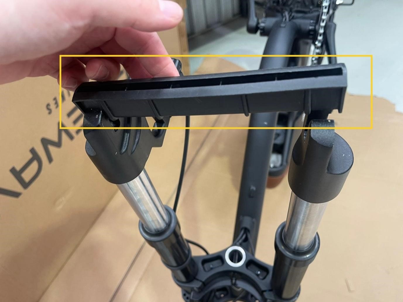
- Invert the Bike Frame – Carefully flip the entire bike frame upside down to make the installation easier and ensure stability for the front wheel installation. Since the bike is heavy, an alternative to flipping it is to securely squeeze the rear brake (left lever) and lift the handlebars while stepping backward. This will gradually position the bike upright on its handlebars and seat, as shown in the image above.
- Remove the Fork Protector – At the bottom of the front fork, there is a plastic protector or spacer to protect the fork during transit. Gently remove this protector to prepare for the wheel installation.
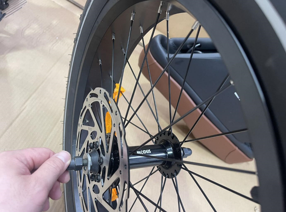
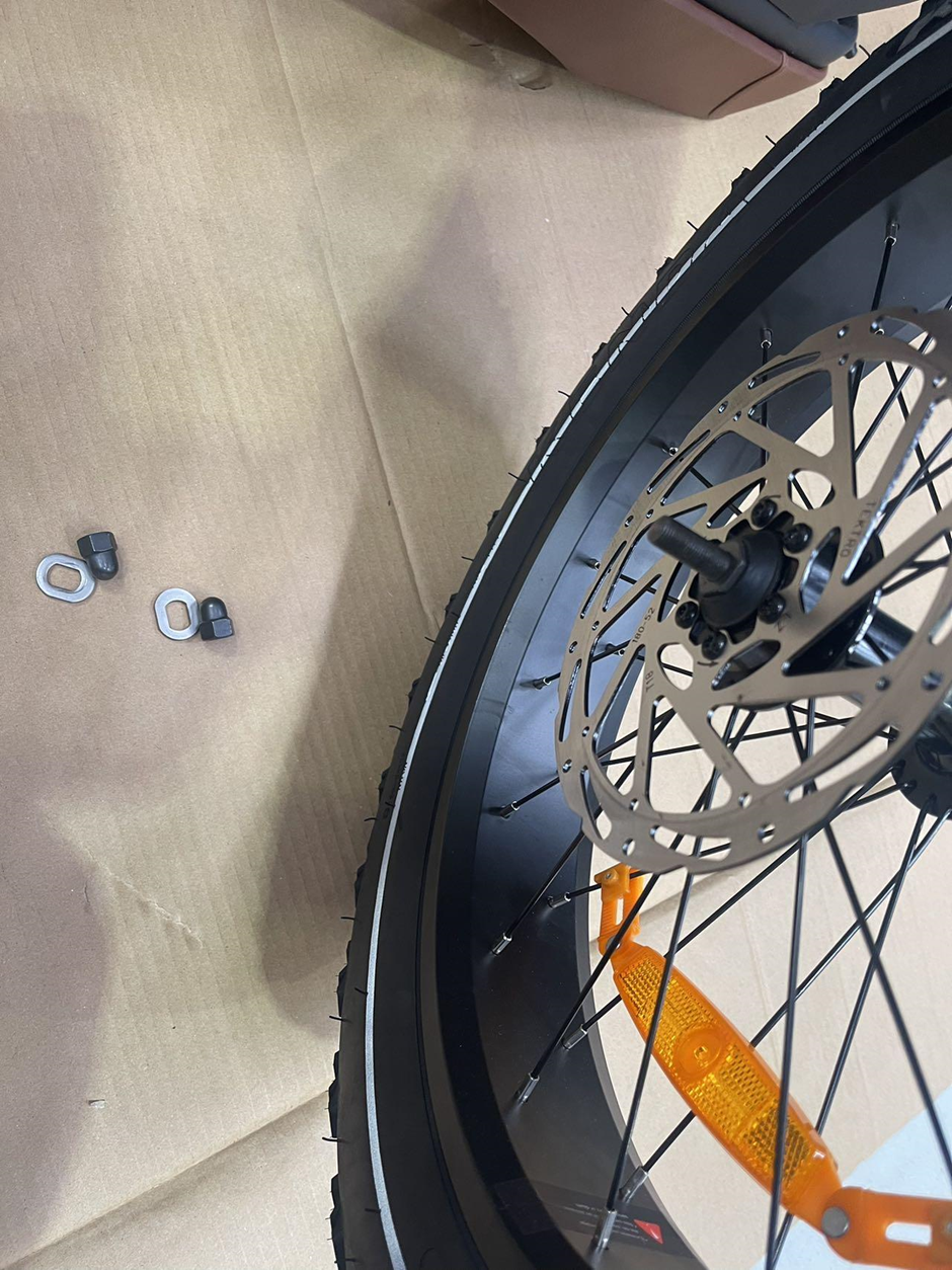
- Remove the Bolts and Washers from the Front Wheel – Locate the bolts and washers on both sides of the front wheel axle (as shown in the image). Carefully unscrew and remove these bolts and washers, setting them aside as you’ll need them to secure the front wheel to the fork.
- Position the Wheel on the Fork – Place the front wheel into the fork slots, ensuring it is properly seated. Align it so the brake disc rotor is on the correct (left) side, sliding into the caliper without any resistance.
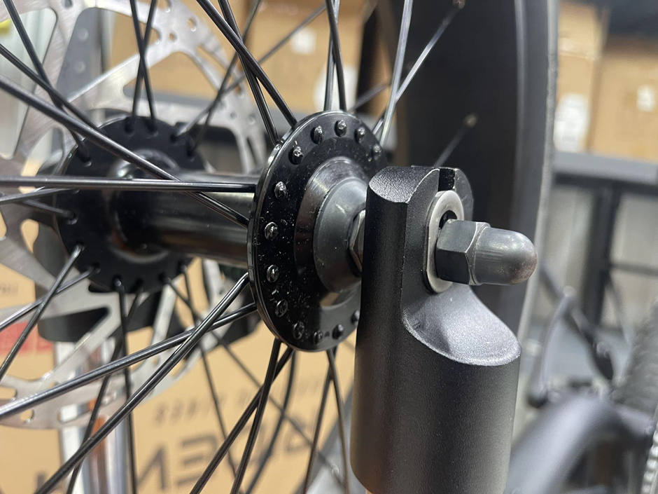
- Secure with Bolts and Washers – With the wheel in place, put the washers and bolts on both sides. Ensure that the washers are positioned outside of the fork on both sides, locking into place correctly. Use the 15mm wrench to tighten the bolts securely, ensuring the wheel is stable and properly aligned with the frame.
- Final Check and Brake Alignment – Once the bolts and washers are fully tightened, check for any excessive friction between the brake disc and the caliper. If there is significant rubbing, try gently adjusting the fork on the caliper side to achieve a slight, even clearance on both sides of the disc within the caliper. If minor rubbing persists, it is recommended to complete the full bike assembly first and then fine-tune the caliper alignment to optimize brake performance.
Important Warning: Brake Disc and Caliper Adjustment
In cases where the brake disc rubs against the caliper, further fine-tuning may be required. We strongly advise that any brake adjustments, especially those involving disc and caliper alignment, be performed by a qualified bike mechanic. The Xplorer Series is equipped with large, precision-cut brake rotors, which are both sharp and capable of causing injury if handled improperly.
If you lack experience in brake adjustments, please seek assistance from a professional bike mechanic at your nearest service center. Attempting to adjust the caliper or disc alignment without proper knowledge and tools is not recommended and may compromise both safety and performance.
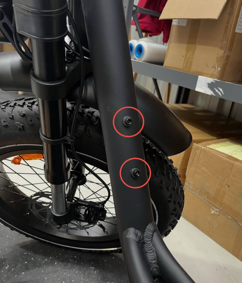
Step 6: Install the front fender
- Tools Required:
- 4mm Hex Key
- 8mm Wrench (10/8mm Wrench in toolkit)
- Loosen the Bolts – Using the 4mm hex key on the bolt end at the mounting point behind the forks, and the 8mm wrench on the nut securing the bolt on the opposite side, carefully remove the bolt from the mounting points on the front fork. This prepares the area for securing the mudguard.
- Position the Mudguard – Align the mudguard’s mounting holes with the mounting points on the fork, ensuring it is centered and clear of the tire.
- Secure the Mudguard – Insert the bolt through the holes and into the mounting point, tightening with the hex key and 8mm wrench for the securing nut. Ensure that the washer sits between the head of the bolt and the mounting point of the mudguard. Be cautious not to overtighten to avoid damaging the mudguard.
- Check Alignment – After securing, ensure the mudguard is straight and does not interfere with the rotation of the front wheel. This can be checked by spinning the front wheel and listening for unwanted noise or any signs of disrupted rotation.
Step 7: Screw in the pedals
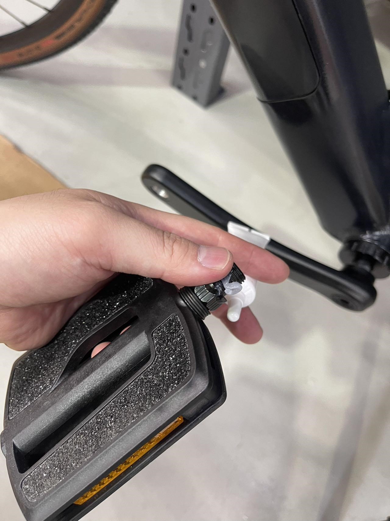
- Tools required:
- 15mm Wrench End (In toolkit)
- 15mm Wrench End (In toolkit)
- Apply grease to the pedal threads - Begin by applying a small amount of grease to the threads of the pedal, as shown in the picture above. This helps prevent the pedals from seizing in the crank and makes future removals easier.
- Attach and tighten the pedals - Insert the pedal into the crank arm and hand-tighten it to ensure it's threaded correctly. Then, use an open-ended 15mm wrench to securely tighten the pedal. Be sure to tighten each pedal in the correct direction: the right (R) pedal tightens clockwise, and the left (L) pedal tightens anticlockwise. This means the direction of tightening should be towards the front of the bike for both pedals.
Step 8: Attach the rear rack
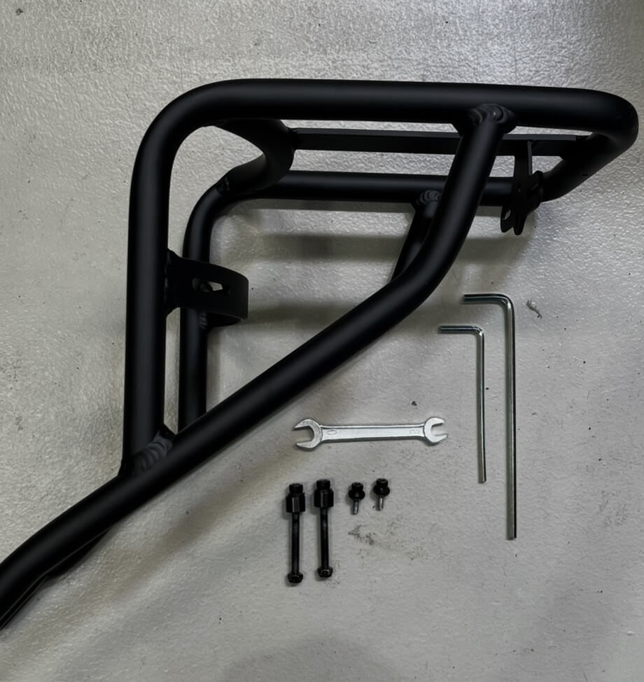
- Tools required:
- 4mm Hex Key
- 5mm Hex Key
- 10mm Wrench (10/8mm Wrench from Toolkit)
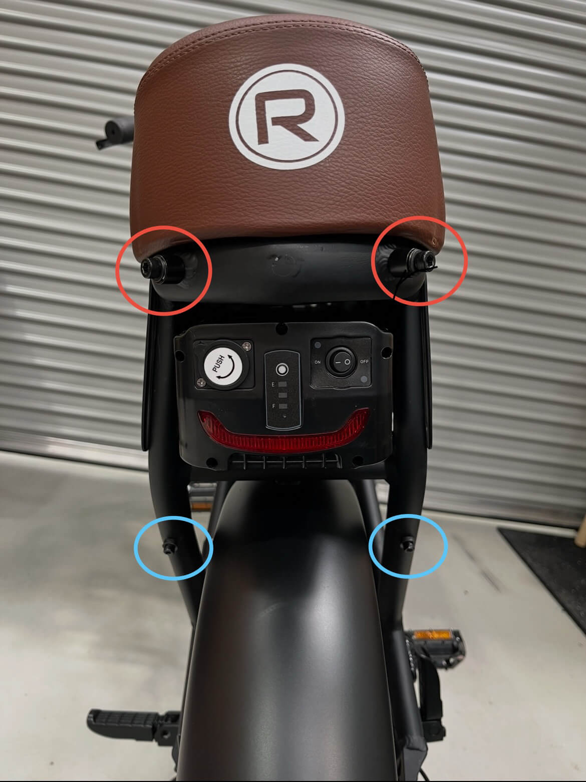
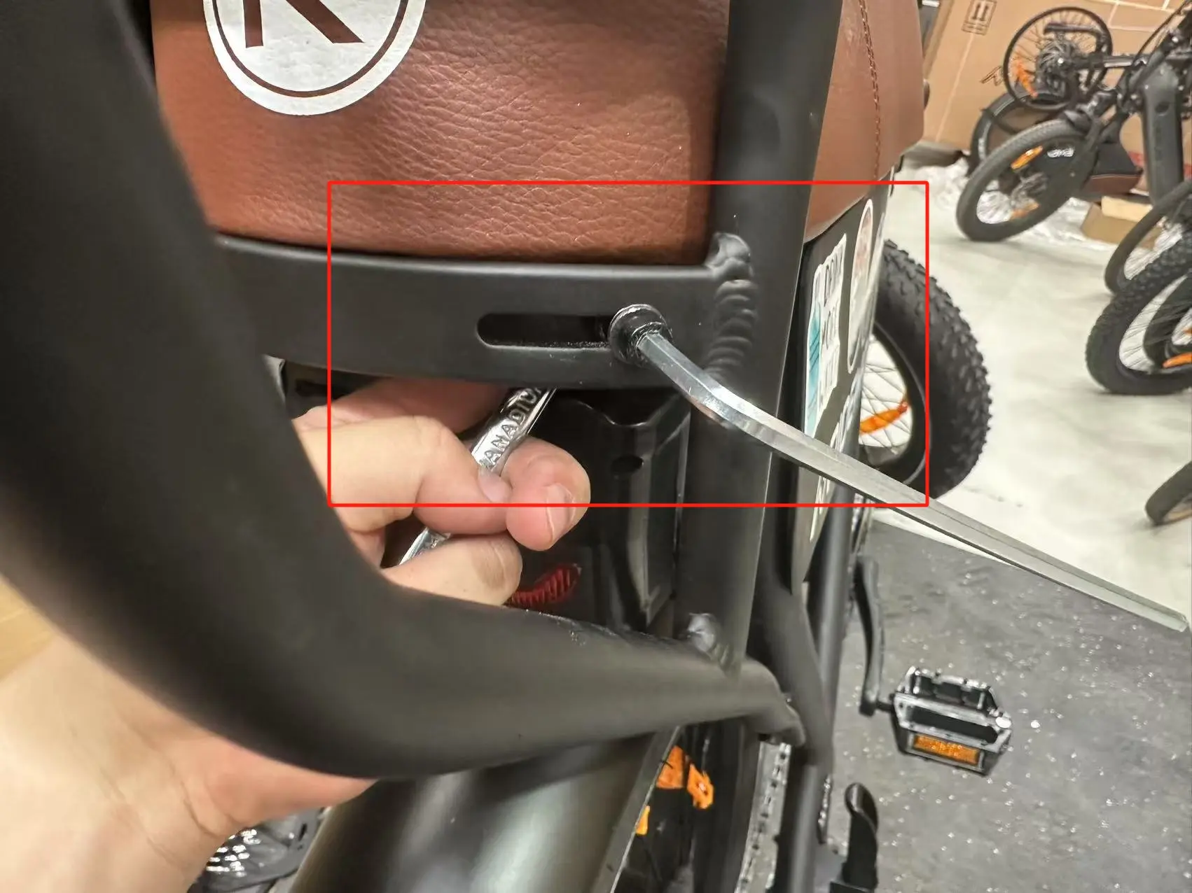
- Remove the existing bolts: Identify the four bolts circled in red and blue on the rear of the bike. Using the appropriate tools, carefully remove these bolts and set them aside for reuse.
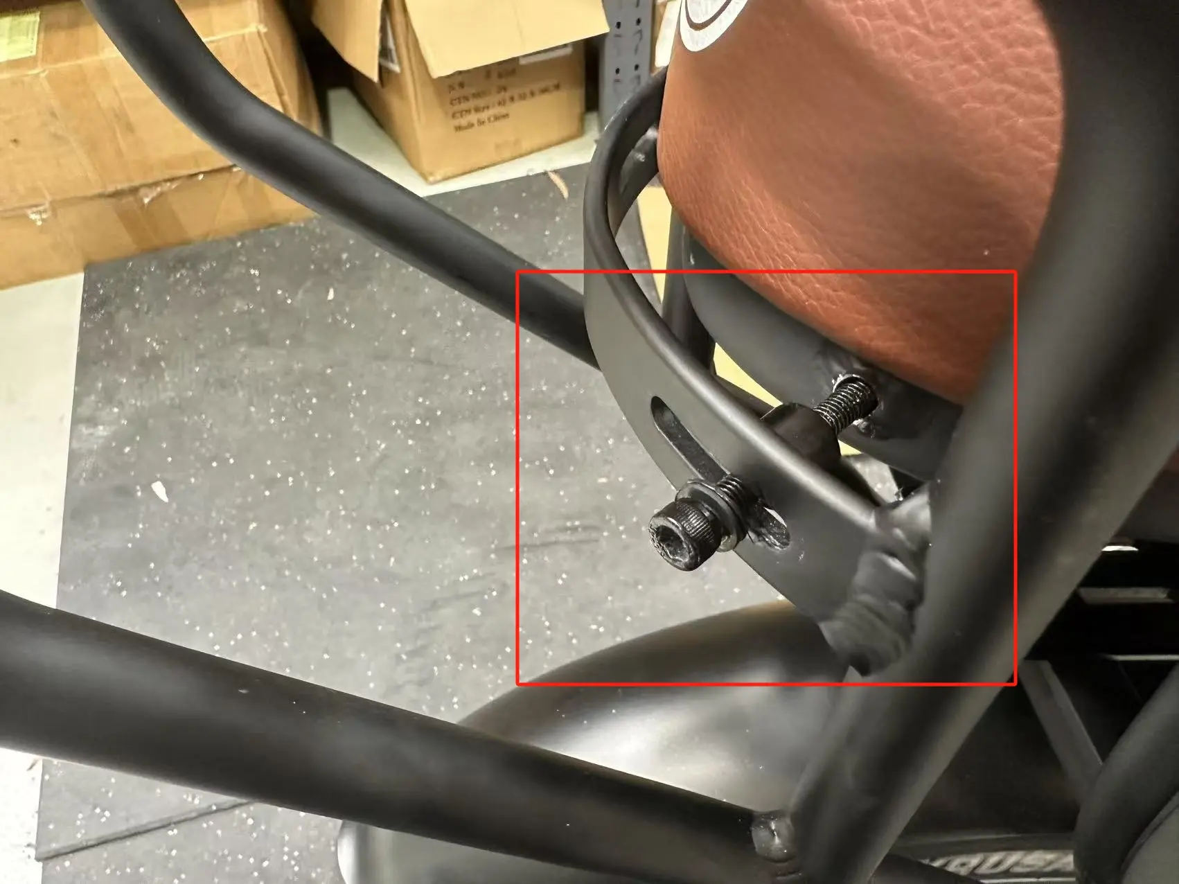
- Position the rear rack: Place the rear rack over the mounting positions, aligning the holes with the bike frame. Insert the two bolts circled in red first and hand-tighten their respective nuts to hold the rack in place. Do not fully tighten at this stage. Use the 4mm hex key to insert the two bolts circled in blue, securing them loosely for now. Refer to the image on the next page for visual representation of how to fasten long bolts (circled red) using wrench and hex key simultaneously.
- Tighten the bolts evenly: Begin by tightening the red bolts at the top using the 10mm wrench and 5mm hex key. Tighten both bolts incrementally, alternating between them to ensure even pressure and proper alignment. Once the red bolts are secure, tighten the blue bolts at the bottom using the 4mm hex key. Again, tighten each bolt slightly in sequence, working evenly until both are fully secured.
- Final checks: Apply gentle pressure to the rack to ensure it is stable and does not move. Verify that all bolts are securely tightened and the rack is properly aligned with the frame. This step is complete once the rear rack is firmly attached and ready for use.
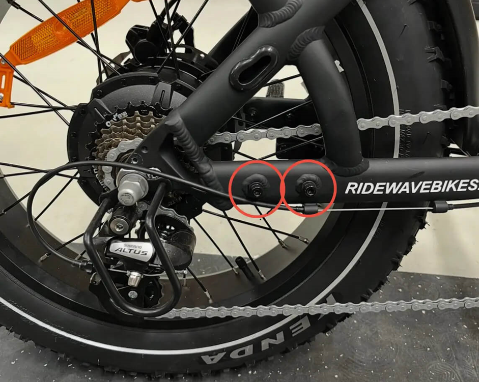
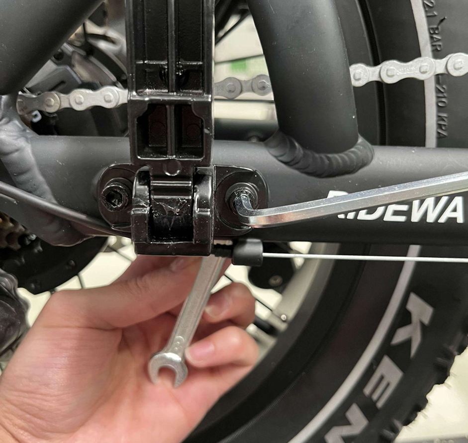
Step 9: Attach the foot pegs
- Tools required:
- 10mm Wrench (10/8mm Wrench from Toolkit)
- 5mm Hex Key
- Remove the existing bolts: Locate the two bolts circled in red on one side of the bike. Using the 5mm hex key and 10mm wrench simultaneously, carefully remove these bolts. Ensure the washers are kept in the same order as the factory configuration (e.g., one washer between the head of the bolt and one between the nut and the frame).
- Position the foot peg: Select one of the footpegs from the accessories box and position it in front of the bolt holes. Align the mounts of the footpeg with the holes, ensuring the footpeg is in the correct orientation (able to fold upward).
- Fasten the foot peg: Insert the bolts through the mounts and tighten them using the 5mm hex key and 10mm wrench. Tighten both bolts securely, ensuring the footpeg is firmly attached to the frame.
- Repeat for the other side: Repeat the same procees on the opposite side of the bike to attach the second footpeg. Tug gently on each footpeg and apply pressure with your foot to confirm they are securely fastened. The footpegs should remain stable and properly aligned throughout this process.
Step 10: Attach the drink bottle holder
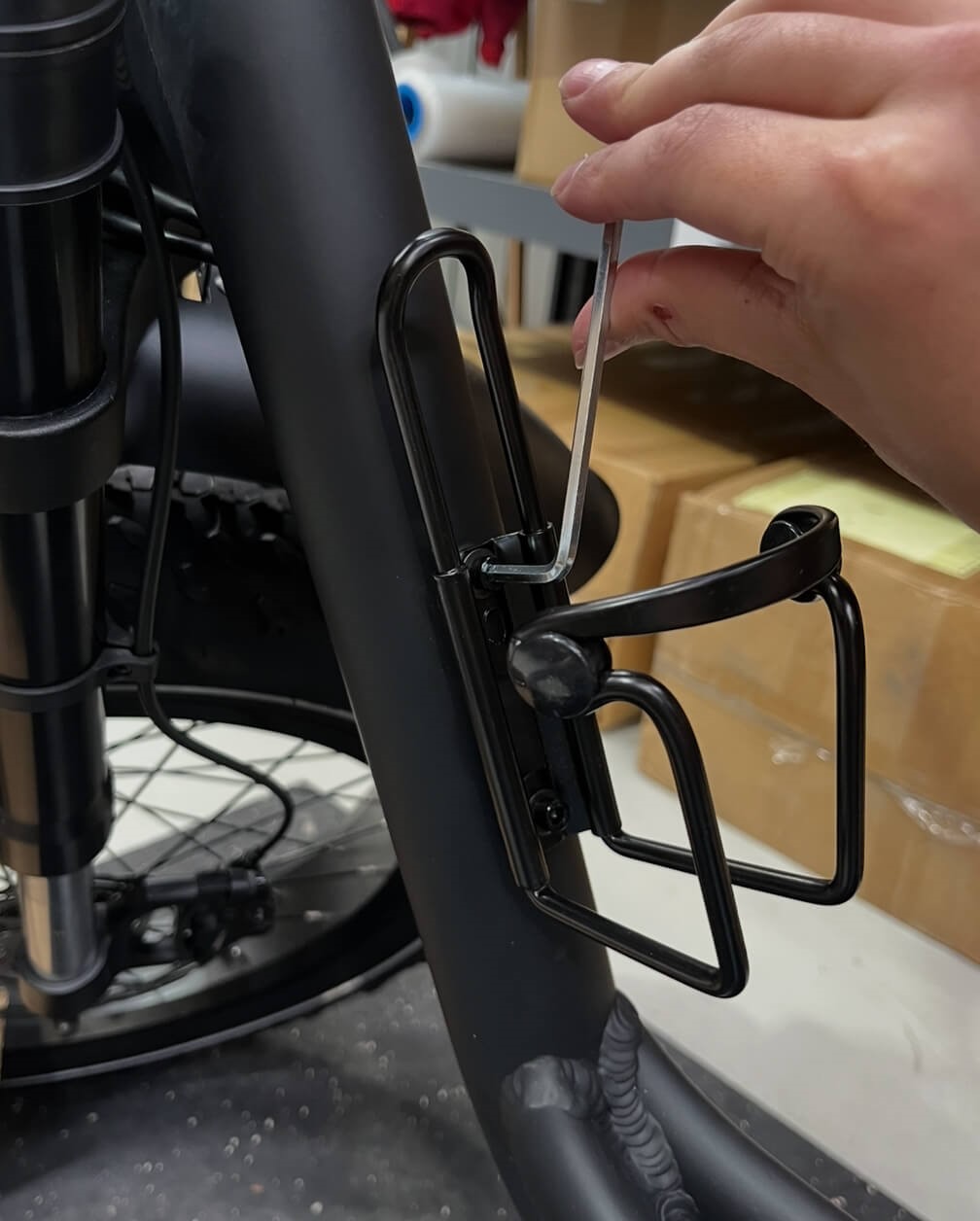
- Tools required:
- 5mm Hex Key
- 5mm Hex Key
- Remove the existing bolts: Locate the two bolts circled in red on the bike frame. Using the 5mm hex key, carefully remove these bolts and set them aside for reuse.
- Position the bottle holder: Align the bottle holder with the bolt mounts on the downtube. Important: Use the very top bolt mount—not the one second from the top. The bottle holder will only align properly with this configuration.
- Fasten the bottle holder: Insert the bolts into the mounting holes and hand-tighten both bolts until they are properly housed in the threading. Finish tightening the bolts securely using the 5mm hex key. Test the bottle holder by applying gentle pressure to ensure it is securely fixed. There should be minimal or no movement when properly attached.
Step 11: Secure the bell to the handlebars
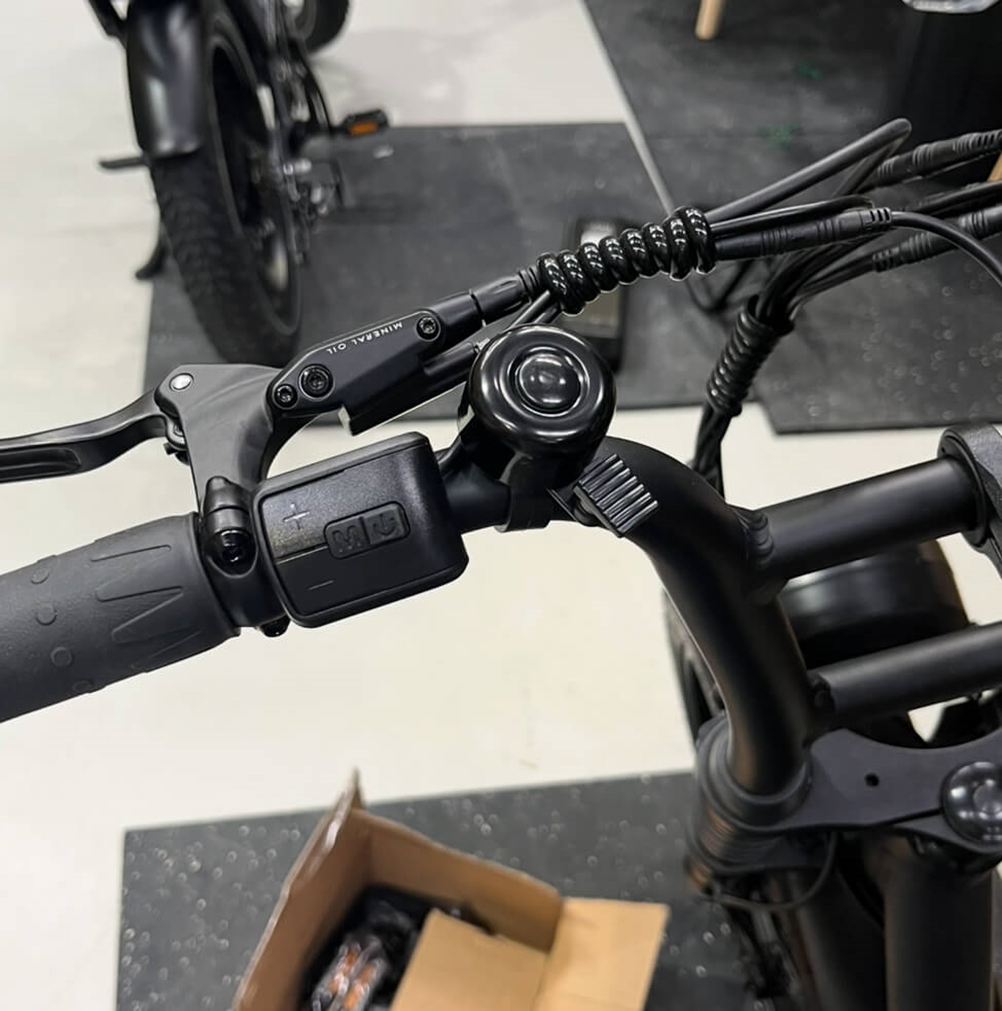
- Tools required:
- Phillips head screwdriver (from toolkit)
- Phillips head screwdriver (from toolkit)
- Unscrew and position the bell: Locate the screw underneath the bell and unscrew it using the Phillips head screwdriver. Position the bell in an empty space on the handlebars. Recommendation: Place the bell on the left side, just past the display button controller. Ensure the bell does not come into contact with other parts such as the gear shifter or brake levers.
- Secure the bell: Once satisfied with the position, insert the screw into the bottom of the bell. Tighten the screw using the Phillips head screwdriver. To make this step easier, flip the bell upside down so the screw faces directly upward. Tighten the screw securely, then flip the bell upright and complete the tightening process.
- Test and adjust: Test the bell by ringing it. Ensure it's securely fastened and does not move when tugged in any direction. If the bell produces a quiet or dampened sound, it may be in contact with another part of the handlebars. Loosen the screw, reposition the bell into an open space, and retighten it.
Step 12: Pumping the tyres
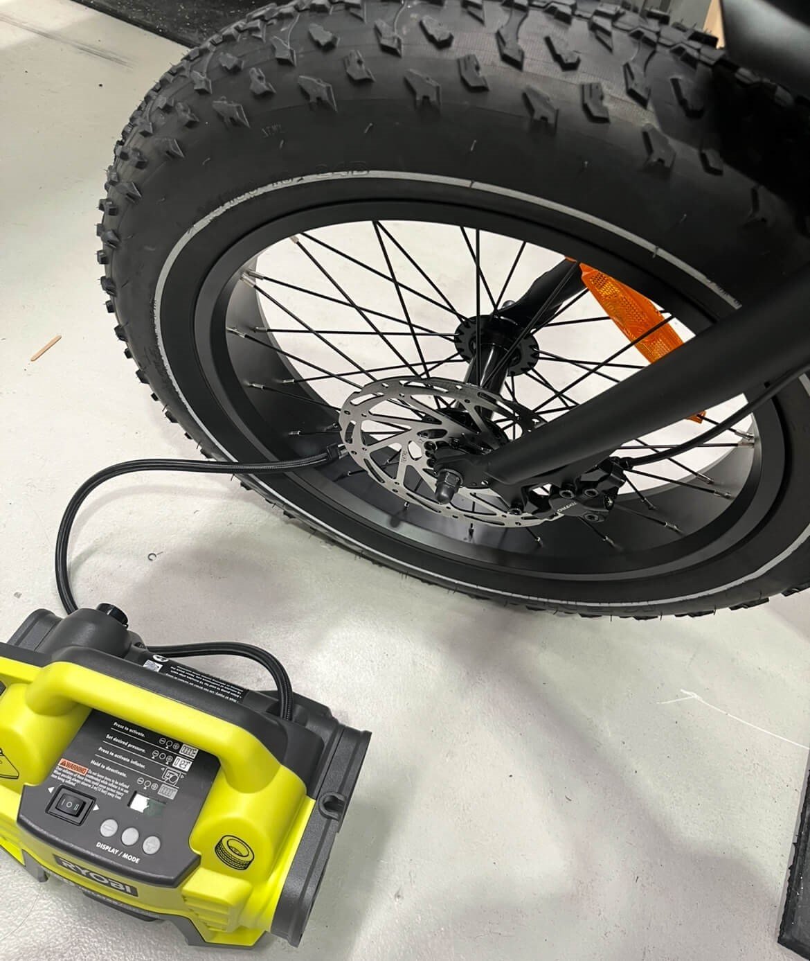
Inflating tyres: Pump both the front and rear tyres to the pressure specified on the tyre sidewall. For the Xplorer, the recommended PSI is between 5-30.
For a Softer Ride: We recommend a PSI range of 5-15 for a smoother, more comfortable ride. This pressure is ideal for the Xplorer base model with rigid forks and is best suited for riders who frequently encounter uneven or off-road terrain.
For a Firmer Ride: If you prefer a sturdier and more responsive feel, aim for a PSI range of 15-30. Higher pressure reduces the frequency of pumping and is better suited for consistently flat terrain, such as urban roads.
Caution in Hot Weather: We do not recommend inflating the tyres beyond 20 PSI during hot summer months, as high temperatures can cause the air inside the tyres to expand, increasing the risk of overinflation, reduced traction, and potential blowouts. Lower PSI settings can help accommodate heat expansion while maintaining comfort and safety.
Finding Your Ideal PSI: Experiment with different pressure levels in the front and rear tires until you discover what feels best for your riding style and terrain. Adjust as needed to achieve your desired balance of comfort and performance.
Important:
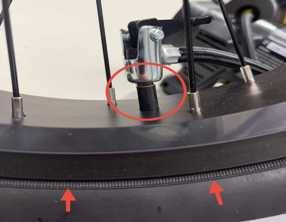
- While inflating, pause occasionally to check that the tyre bead (indicated with arrows) is properly seated around the rim.
- Ensure that the pumping nozzle is correctly attached to the inner tube valve, air should escape before the lever is adjusted. (Proper attachment circled in red)
- If the bead starts to rise unevenly, deflate the tyre slightly and press the bead back into place before continuing.
- Ensure the tyre bead line (a thin moulded line near the sidewall) is evenly positioned just above the rim on both sides.
- If any part of the inner tube becomes exposed during inflation, stop immediately as this can cause the tube to burst.
Properly seating the bead ensures safe and consistent tyre inflation.
Final Steps:
Once the bike is assembled, it will need some fine-tuning and basic adjustments. The following links are the most common areas needing adjustment within the first few miles.
Adjust the derailleur - https://www.parktool.com/en-us/blog/repair-help/rear-derailleur-adjustment
Bed the brakes - https://www.youtube.com/watch?v=iUV2Eo9ERSk
Adjust the brakes - https://www.youtube.com/watch?v=uk_nC9anQcM
For any further questions, please reach out to support via the contact form: https://ridewavebikes.com.au/pages/contact-us
Important Reminder About Bike Security
To protect your bike, make sure to record its serial number before use. This is essential for filing a police report in case of theft, as we do not track serial numbers for individual orders.
We highly recommend investing in a high-quality lock to secure your bike, such as ABUS or Kryptonite U-locks. A good rule of thumb is to spend around 5% of the bike's price on a reliable lock.
For added security, consider these additional measures:
- Install an Apple AirTag under the bike seat for tracking in case of theft.
- Use a disk brake lock to immobilize the bike.
- Install a bike alarm system to sound a siren if the bike is moved.
- Insure your e-bike through companies offering e-bike insurance in Australia.
In most cases, theft of bike parts (e.g., saddle, tires, LCD display) is rare, as these parts are usually not compatible with other brands and have limited resale value. Therefore, focus on securing the bike frame rather than individual components.
Electric bike theft is unfortunately common in Australia. Even with top-tier locks and security systems, no bike is completely theft-proof. To minimize risk, avoid leaving your bike in public spaces for long periods or overnight.